
-
What brand of IGBT module is used in your company’s frequency converter?
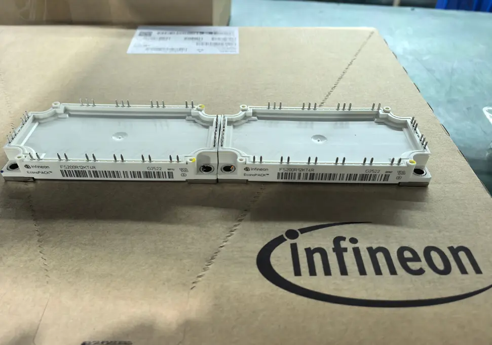
Our Inverters Use German Infineon IGBT Modules
Why We Choose Infineon IGBT Modules
Market Leadership
Advanced Technology
Quality Assurance
Benefits for Your Business
Enhanced Performance
Cost Savings
Technical Support and Service
Next Steps
-
How to Real-Time Monitor the Quality of Inverter Raw Materials During Production
I. Clarify Monitoring Objects: List of Core Inverter Raw Materials (Priority Categories for Control)
II. Real-Time Monitoring Solutions by Raw Material Type (Technical Methods + Implementation Steps)
1. Power Semiconductors (IGBTs/Rectifier Bridges): Focus on “Soldering Quality + Temperature Rise Stability”
2. Capacitors (Bus Capacitors/Filter Capacitors): Focus on “Capacitance Drift + Leakage Current”
3. PCB Boards (Main Control/Power Boards): Focus on “Conductivity + Insulation”
4. Magnetic Components (Inductors/Transformers): Focus on “Inductance + Temperature Rise”
III. Build a Real-Time Monitoring Support System (Ensure Data Closure and Abnormality Traceability)
1. Data Collection and Analysis System (Core Support)
2. Abnormality Response Mechanism (Rapid Handling)
3. Full-Process Traceability Mechanism (Responsibility Localization)
-
How to Ensure the Quality Stability of Raw Materials Throughout the Production Process
To ensure the quality stability of raw materials throughout the production process, it is essential to establish a “full-process closed-loop management and control system”—from source selection of raw materials before warehousing, to real-time monitoring during production, and to traceability and review after finished products are shipped. Each stage requires clear standards, defined responsibilities, and technical support, with the core principle of “prevention-oriented, process controllable, and abnormalities traceable”. Below are 6 key stages, each with specific, actionable implementation plans:
I. Source Control: Establish a Supplier Access and Classification System (Start with “Selecting the Right Suppliers”)
The quality of raw materials depends fundamentally on suppliers. A strict access mechanism is required to screen qualified partners and prevent “inferior raw materials from entering production”.1. Supplier Access Audit (Threshold Pre-Setting)
- Develop a Supplier Access Standard and clarify mandatory requirements:
-
- Qualification verification: Suppliers must provide production licenses, industry certifications (e.g., SC certification for food raw materials, RoHS certification for electronic components), and quality inspection reports from the past 3 years;
-
- Production capacity and stability: Assess production scale (to ensure it matches the enterprise’s needs), equipment accuracy (e.g., calibration records for reactors used in chemical raw material production), and historical delivery performance (no more than 2 stock-outs or delays in the past year);
-
- Quality control capabilities: Require suppliers to share their internal raw material inspection processes (e.g., whether they have an Incoming Quality Control (IQC) process) and abnormality handling mechanisms (e.g., return and exchange procedures for unqualified raw materials).
- On-site inspections: Conduct on-site visits to suppliers of core raw materials (e.g., key chemical additives that affect product performance, electronic components). Verify whether their production environment (e.g., clean room standards for food raw material factories) and testing equipment (e.g., availability of gas chromatographs, spectrometers, and other precision instruments) meet requirements.
2. Supplier Classification Management (Dynamic Optimization)
- Classify suppliers into three levels—Grade A (core), Grade B (qualified), and Grade C (alternative)—based on “quality stability, delivery rate, and service response speed”:
-
- Grade A suppliers: Account for no more than 30% of total suppliers. Offer priority procurement (allocate ≥60% of total orders) and preferential payment terms (e.g., extend payment cycles from 30 days to 45 days);
-
- Grade B suppliers: Account for 60% of total suppliers. Serve as regular procurement partners and conduct monthly quality data evaluations;
-
- Grade C suppliers: Account for ≤10% of total suppliers. Used only as backups. If a Grade B supplier’s pass rate falls below 98% for 3 consecutive months, demote them to Grade C and require rectification.
- Update supplier quality ledgers monthly: Record the inspection pass rate and number of abnormalities for each batch of raw materials. Track and urge rectification for underperforming suppliers.
II. Incoming Inspection: Establish a “Dual Verification” Mechanism (Block Unqualified Raw Materials)
Raw materials must undergo strict inspection before warehousing to prevent “storage of defective materials”. The core is to “set clear standards, adopt scientific sampling, and conduct comprehensive testing”.1. Develop Clear Inspection Standards (IQC Standards)
- Create an Incoming Inspection Specification (SOP) for each type of raw material, specifying “inspection items, qualified ranges, testing methods, and judgment rules”:
-
- Example 1 (Metal raw materials): Inspection items include “component content (e.g., Cr content ≥18% for stainless steel), dimensional tolerance (e.g., thickness deviation ≤±0.02mm), and surface defects (no scratches or rust spots)”. Testing methods include “using spectrometers for component analysis, micrometers for dimensional measurement, and visual inspection for surface defects”;
-
- Example 2 (Food raw materials): Inspection items include “sensory indicators (normal color and odor), physical and chemical indicators (moisture content ≤15%), and microbial indicators (total bacterial count ≤1000 CFU/g)”. Testing methods refer to national GB standards.
- Share these standards with suppliers to avoid disputes caused by “inconsistent understanding of qualified standards between the supply and demand sides”.
2. Scientific Sampling and Testing (Avoid Missed Inspections or Misjudgments)
- Sampling rules: Refer to GB/T 2828.1 (Sampling Procedures for Inspection by Attributes) and determine sampling ratios based on batch size (e.g., sample 5 pieces for batches of ≤100 pieces, 10 pieces for batches of 100–500 pieces). Focus on “easily fluctuating indicators” (e.g., purity of chemical raw materials, concentration of liquid raw materials);
- Dual testing: IQC specialists conduct on-site testing for routine indicators (e.g., dimensions, appearance). For key indicators (e.g., component content, microbial levels), send samples to laboratories for testing with precision instruments (e.g., high-performance liquid chromatographs, atomic absorption spectrophotometers). Archive test reports for future reference;
- Abnormality handling: If sampling fails, immediately initiate “secondary sampling” (double the sampling ratio). If the second sampling also fails, classify the entire batch as unqualified, prohibit warehousing, require suppliers to return or replace the goods, and record the incident in the supplier quality ledger.
III. Storage Management: Control Environmental Variables (Prevent Raw Material Deterioration or Performance Degradation)
Different raw materials have distinct storage requirements. Improper storage can lead to quality degradation (e.g., metal rusting, plastic aging, food moisture absorption). The key is to “store by category, monitor the environment, and follow the first-in-first-out (FIFO) principle”.1. Classified and Zoned Storage (Determine Storage Conditions Based on Characteristics)
- Divide storage areas by raw material characteristics and define environmental requirements:
-
- Temperature- and humidity-sensitive materials (e.g., electronic components, pharmaceutical raw materials): Store in constant-temperature, constant-humidity warehouses. Control temperature at 20±5℃ and humidity at 40%–60%. Equip warehouses with temperature and humidity recorders for real-time monitoring and automatic alarms;
-
- Corrosion- or oxidation-prone materials (e.g., metal plates, chemical reagents): Store in sealed warehouses. Coat metal raw materials with anti-rust oil or wrap them in anti-rust paper. Store chemical reagents separately and away from fire sources;
-
- Food-grade raw materials: Store in clean warehouses, isolated from non-food raw materials. Install UV disinfection equipment in warehouses and conduct regular cleaning (once a week).
- Clear labeling: Attach labels to each storage area and shelf, indicating “raw material name, specification, warehousing date, shelf life, and storage requirements”. This avoids misplacement or confusion (e.g., mixing ordinary plastics with food-grade plastics).
2. Implement the “First-In-First-Out (FIFO)” Principle
- During warehousing, sort raw materials by “production date/warehousing date”. Place earlier incoming raw materials near the warehouse exit;
- During outbound processing, prioritize the use of the earliest incoming raw materials. This prevents raw materials from exceeding their shelf life or deteriorating due to prolonged storage (e.g., rubber raw materials tend to harden after 6 months of storage, which affects subsequent processing);
- Regular inventory checks: Conduct monthly inventory checks of stored raw materials. Inspect for expired, deteriorated, or abnormally stored materials (e.g., damaged packaging). Isolate and handle problems immediately upon discovery.
IV. Production Process: Real-Time Monitoring and Process Adaptation (Reduce Quality Fluctuations During Processing)
Raw materials are affected by processing techniques, equipment status, and operating methods during production. It is necessary to “monitor key nodes, adapt to process parameters, and intervene in abnormalities promptly” to ensure raw materials still meet quality requirements after processing.1. Monitor Key Process Nodes (Target Stages Affecting Raw Material Quality)
- Identify “stages with the greatest impact on raw material quality” in the production process and set up monitoring points:
-
- Example 1 (Plastic injection molding): During the raw material melting stage, monitor “melting temperature (e.g., 180–220℃ for PP materials) and screw speed (50–80 rpm)”. Excessive temperature causes raw material degradation, while insufficient temperature leads to incomplete melting;
-
- Example 2 (Metal stamping): During the stamping stage, monitor “stamping pressure (e.g., 100–120 MPa) and mold temperature (25±5℃)”. Excessive pressure causes metal deformation, while insufficient pressure prevents proper forming.
- Use automated equipment to collect data in real time (e.g., temperature sensors, pressure sensors). Trigger alarms immediately when data exceeds the qualified range and stop production to investigate the cause (e.g., changes in melting temperature adaptability due to different raw material batches).
2. Adapt Raw Material Batches to Process Parameters (Avoid “One-Size-Fits-All”)
- Small differences may exist between different batches of raw materials (e.g., particle size, density), so process parameters need to be adjusted based on actual conditions:
-
- Example: A textile factory uses two batches of cotton yarn. Batch A has a moisture content of 12%, while Batch B has a moisture content of 8%. If the same drying temperature (80℃) is used for both, Batch A remains damp after drying, and Batch B becomes brittle due to over-drying. To solve this, adjust the drying temperature to 85℃ for Batch A and keep it at 80℃ for Batch B. This ensures the moisture content of both batches is controlled at 6%–8% after drying.
- Establish a “raw material batch-process parameter” correspondence table. Record the optimal process parameters for each batch of raw materials. Reuse these parameters for subsequent batches of the same raw material to reduce debugging time and quality fluctuations.
V. Finished Product Traceability: Establish a “Raw Material-Finished Product” Correlation System (Facilitate Problem Tracing and Improvement)
If quality issues occur with finished products, it is critical to quickly trace the corresponding raw material batches and identify the root cause (e.g., unqualified raw materials, abnormal processing stages). The core is to “assign unique codes throughout the process, correlate data, and enable quick queries”.1. Assign Unique Codes to Raw Materials and Finished Products (Unique Identification)
- Assign a unique “raw material batch code” (e.g., “MAT-20240528-001”, including the date and batch number) to each batch of raw materials during warehousing;
- During production, correlate the “raw material batch code” with the “finished product traceability code” (e.g., “PROD-20240528-001”). Record this correlation in the Manufacturing Execution System (MES) to enable reverse traceability from “finished products to the raw material batches used”;
- Coding methods: Use barcodes, QR codes, or RFID tags. Scanning the code allows quick access to information such as raw material batches, incoming inspection reports, and production process parameters.
2. Trace Quality Issues and Drive Improvements (Closed-Loop Management)
- If finished products fail inspection (e.g., insufficient strength in a batch of parts), use the finished product traceability code to find the corresponding raw material batch. Check the incoming inspection report for that batch (e.g., whether there were component non-conformities) and the production process parameters (e.g., whether there was insufficient stamping pressure);
- If the issue is confirmed to be caused by raw materials (e.g., the tensile strength of the metal raw material batch is below the standard), immediately stop using the remaining raw materials of that batch, recall finished products that have entered the market, and require the supplier to rectify the problem. If the issue is caused by processing (e.g., low stamping temperature), optimize the process parameters and provide training for operators;
- Regular reviews: Monthly statistics on “finished product non-conformity rates related to raw materials”. Analyze high-frequency issues (e.g., persistently high non-conformity rates for a specific type of raw material) and optimize suppliers or inspection standards accordingly (e.g., add component testing items for that type of raw material).
VI. Continuous Improvement: Optimize the Management System Based on Data (Ensure Long-Term Stability)
Quality management is not static. Regular data analysis is needed to identify weaknesses and drive optimizations, with the core of “data-driven, regular evaluation, and continuous iteration”.1. Data Statistics and Analysis (Identify Weaknesses)
- Regularly collect and analyze key indicators:
-
- Raw material side: Supply pass rate of each supplier, incoming non-conformity rate of different raw materials, and deterioration rate of stored raw materials;
-
- Production side: Finished product pass rate for different raw material batches, number of process parameter adjustments, and number of raw material quality abnormalities during production;
- Visualize data with charts (e.g., bar charts to compare the pass rates of different suppliers, line charts to track changes in the non-conformity rate of a specific raw material). Identify weaknesses (e.g., a supplier with a persistently low pass rate, a type of raw material with a high storage deterioration rate).
2. System Optimization (Targeted Improvements)
- Address supplier issues: Require suppliers with low pass rates to submit rectification plans. Eliminate suppliers that fail to rectify the problem and introduce new suppliers to fill gaps;
- Address inspection issues: If a type of raw material passes incoming inspection but causes quality fluctuations during production, optimize the inspection standards (e.g., add “processing adaptability testing” for the raw material to simulate production conditions and test its performance);
- Address storage issues: If a type of raw material has a high deterioration rate in storage, improve storage conditions (e.g., add dehumidification equipment, replace packaging with more sealed options);
- Regular audits: Conduct quarterly audits of the Supplier Access Standard, Incoming Inspection Specification, and Storage Management Specification. Revise these documents based on updates to industry standards (e.g., new national raw material safety standards) and changes in enterprise production needs (e.g., special raw materials for new products).
Summary: Core Logic
Ensuring the quality stability of raw materials throughout the production process essentially involves establishing a “full-process closed-loop management and control system from source to finished products”—by “selecting the right suppliers” (source), “blocking unqualified raw materials” (incoming inspection), “preventing storage deterioration” (storage), “controlling processing fluctuations” (production), “enabling traceability and improvement” (traceability), and “driving optimization with data” (continuous improvement). Each stage has clear standards, monitoring mechanisms, records, and improvement measures. This ultimately minimizes raw material quality fluctuations and maximizes the quality stability of finished products. -
What Is the Approximate Lead Time for Customized Inverters?
-
How We Ensure Product Quality in Inverter Production
In the inverter production process, we ensure product quality through strict full-process and multi-dimensional control, with specific measures covering the following five core links:- Source Control of Raw Materials
Core components (such as IGBT modules, capacitors, and chips) are exclusively procured from internationally renowned brands to eliminate the risk of inferior materials at the source. All raw materials must undergo precise electrical parameter testing and comprehensive visual inspection before entering the warehouse. Additionally, we maintain a list of qualified suppliers and conduct regular evaluations to ensure consistent supply chain quality.- Precise Control of the Production Process
Automated Optical Inspection (AOI) technology is applied in the Surface Mount Technology (SMT) assembly process to identify solder paste defects and component misalignment in real time. After wave soldering, X-ray testing is performed to thoroughly inspect for solder joint quality issues (e.g., cold joints, voids). The entire production line is equipped with an Electrostatic Discharge (ESD) protection system to prevent electrostatic damage to sensitive components. We set up dedicated quality control checkpoints for key processes and implement 100% full inspection to block unqualified semi-finished products from moving to the next process.- Comprehensive Functional and Performance Testing
All inverters are required to complete 100% load burn-in testing—operating at full load in a high-temperature environment (typically 45–60°C) for 24–48 hours to verify long-term stability. Electrical safety tests are conducted, covering critical items such as withstand voltage (1.5kV AC for 1 minute), insulation resistance (≥100MΩ at 500V DC), and ground resistance (≤0.1Ω), to ensure compliance with electrical safety standards. Performance parameters, including frequency accuracy (±0.1%), voltage regulation (±0.5%), and current precision (±1%), are precisely calibrated to guarantee reliable operational performance. We also conduct environmental adaptability tests (including high-low temperature cycles, humidity exposure, and vibration resistance) to validate the product’s reliability under complex working conditions.- Full-Lifecycle Quality Traceability
Each inverter is assigned a unique serial number, enabling full-lifecycle tracking from raw material procurement to after-sales service. We record and archive the entire production process data in real time—including raw material batch numbers, production process parameters (e.g., soldering temperature, inspection results), and final test reports. When traceability is required, the complete manufacturing history of any inverter can be retrieved quickly and accurately, facilitating efficient problem localization and resolution.- After-Sales Feedback and Continuous Optimization
We have established a fast-response mechanism for customer feedback, ensuring that quality-related issues are addressed within 24 hours of receipt. Our quality team conducts regular analysis of after-sales quality data to identify potential improvement points (e.g., component failure trends, user operation-related issues). Based on feedback results and test data, we continuously optimize product design (e.g., enhancing heat dissipation structures) and production processes (e.g., upgrading soldering parameters), forming a closed-loop quality improvement cycle of “production-feedback-optimization”.In addition, we hold the ISO 9001 Quality Management System certification, and our inverters comply with international standards such as CE (for the European market) and RoHS (for environmental protection requirements). For OEM customers, we can also provide customized additional quality control measures (e.g., dedicated inspection teams) or third-party testing services (e.g., TÜV and UL certification testing) to further strengthen quality assurance for their specific markets. -
Our VFD OEM Service Quality Control Process
We implement a strict quality control process for our inverter OEM services, covering the following key stages:1. Raw Material Control- Core components (including IGBT modules, capacitors, and chips) are sourced exclusively from international renowned brands
- Rigorous electrical parameter testing and visual inspection are conducted before warehouse entry
- A qualified supplier list is maintained, with regular performance evaluations to ensure consistency
2. Production Process Control- Automated Optical Inspection (AOI) is applied during the SMT (Surface Mount Technology) assembly process
- X-ray testing is performed after wave soldering to guarantee solder joint quality
- The entire production line is equipped with an ESD (Electrostatic Discharge) protection system
- Quality checkpoints are set at key processes, with 100% inspection to eliminate defects
3. Functional & Performance Testing- 100% load burn-in testing (full-load operation in a high-temperature environment) is carried out
- Electrical safety tests are conducted, including withstand voltage, insulation resistance, and ground resistance tests
- Performance parameters (such as frequency, voltage, and current accuracy) are calibrated precisely
- Environmental adaptability tests are performed to verify resistance to extreme temperatures, humidity, and vibration
4. Quality Traceability System- Each product is assigned a unique serial number for full lifecycle tracking
- Comprehensive production data is recorded and archived in real time
- The manufacturing history of any product can be traced quickly and accurately
5. After-sales Quality Feedback- A fast-response mechanism is established to address customer feedback promptly
- Regular quality data analysis is conducted to identify improvement opportunities
- Design and production processes are continuously optimized based on feedback and test results
We hold ISO 9001 quality management system certification, and our products comply with international standards such as CE and RoHS. For OEM customers, we can also provide additional quality control measures or third-party testing services tailored to your specific requirements. -
Your company can provide OEM customization of frequency converters?
-
DreamWe inverter performance? Measured performance and user evaluation analysis
DreamWe inverter performance? Measured performance and user evaluation analysis
In the industrial equipment and pump control system, the performance of the inverter directly affects the operating efficiency and stability of the equipment.DreamWe as a brand focusing on frequency conversion technology, its inverter performance in the market has attracted much attention. In this paper, we will analyze the actual performance of DreamWe inverter through actual measurement data and user feedback, and provide reference for users who have the need to choose and buy.
First, a wide range of adaptability: covering multiple types of pumps and voltage scenarios
One of the core advantages of DreamWe inverters lies in its strong adaptability. Tests show that whether it is a family or small industrial scenes commonly used single-phase 220V water pump (such as water pumps, small submersible pumps), or large industrial equipment equipped with three-phase 380V water pumps (such as centrifugal pumps, deep-well pumps), it can be stable and compatible.
In the test of different power pumps, single-phase water pumps below 1.5kW connected to DreamWe inverters, the peak starting current was reduced by about 30% compared with direct starting, effectively reducing the impact on the power grid; while 380V centrifugal pumps above 5.5kW were adapted and the voltage fluctuation during operation was controlled to within ±2%, with no shutdowns caused by unstable voltage. This means that DreamWe inverters can provide reliable support for both low-power civil and high-power industrial scenarios.
Test Performance: Efficiency, Stability and Energy Saving
1. Operation Efficiency: Enhancing the Working Efficiency of Water Pumps
In a continuous 8-hour running test for a 1.1kW single-phase submersible pump, the conversion efficiency of DreamWe frequency converter is stable at more than 95%, which is 3%-5% higher than that of ordinary frequency converters. Its vector control technology can adjust the motor speed in real time, so that the pump automatically reduces its speed when the flow demand is low, avoiding the waste of energy caused by the “big horse and small car”. Data show that under the same working conditions, the average daily power consumption of water pumps using DreamWe frequency converter is about 12% less than that of traditional control methods.
2. Stability: Ability to cope with complex working conditions
In the test of simulated voltage fluctuation (voltage fluctuates between 180V-240V in 220V scenario, and between 340V-410V in 380V scenario), the over-voltage/under-voltage protection of DreamWe frequency converter responds quickly, and the protection mechanism can be triggered within 0.3 seconds to prevent the pump motor from burning due to the abnormal voltage. Meanwhile, in the humid environment (85% humidity) and dusty environment, its sealing design effectively prevents the components from moisture or dust accumulation, and it runs continuously for 30 days without failures.
3. Intelligent Functions: Simplify Operation and Monitoring
DreamWe inverters are equipped with LED displays that can show parameters such as speed, current and temperature in real time, so that users can keep track of the operating status without additional equipment. Some models support remote control function, and through the cell phone APP, users can adjust the speed of the pump or check the fault code. This design is especially well received in industrial scenarios, which reduces the cost of manual inspection.
User Evaluation: Feedback from Real Scenarios
1. Feedback from Industrial Users
The person in charge of a chemical factory, which purchased three DreamWe 380V inverters for controlling 6kW centrifugal pumps, said, “In the past half year of operation, the equipment has never been shut down due to inverter failure, and the monthly electricity cost has saved nearly 2,000 yuan compared with the previous brand, so the stability and energy saving have exceeded expectations. Stability and energy saving are beyond expectation.”
2. Feedback from Civil Scene
A farmer who installed a 220V water pump mentioned: “The voltage at home is not too stable, and the water pump often tripped in the past, but after replacing the DreamWe frequency converter, even if the voltage fluctuates, the water pump works normally, and the pumping speed is more uniform than before.” 3.
3. Maintenance master evaluation
engaged in water pump maintenance for many years, Mr. Wang said: “DreamWe inverter failure rate is very low, and occasional problems, the fault code is clear, troubleshooting is very convenient, and it is very friendly to our maintenance staff.”
Fourth, summarize: DreamWe inverter is worth choosing?
From the measured data and user feedback, DreamWe inverter is outstanding in terms of adaptability, efficiency and stability, especially in the scenario of large voltage fluctuations, the advantages are obvious, and the energy-saving effect has been verified in multiple scenarios. Whether it is a small power pump for civil use or a high-power device for industrial use, DreamWe can provide reliable control support. If you are looking for an inverter that combines performance and cost-effectiveness, DreamWe is undoubtedly worth considering! -
How about the DreamWe brand inverter?
We can introduce the inverter from the aspects of speed regulation performance, energy saving effect, protection function, compatibility, etc. The following are the details:
Excellent speed regulation performance: Our inverter adopts advanced control technology, which can adjust the proportional relationship between output voltage and frequency in real time according to load requirements. It has a wide speed regulation range, high precision, fast response speed, and can accurately meet the control requirements of motor speed under different working conditions.
Significant energy saving effect: It can automatically adjust the power supply voltage and frequency according to the actual load of the motor, so that the motor can run efficiently even at low load and reduce energy loss. For equipment such as pumps and fans, the power consumption of the motor is proportional to the cube of the speed. The frequency conversion speed regulation can greatly save electricity.
Perfect protection function: It has multiple protection functions such as overcurrent, overvoltage, overload, overheating, undervoltage, short circuit, etc. When the motor or inverter is abnormal, it can quickly detect and cut off the power supply or reduce the motor speed, effectively preventing equipment damage and ensuring safe and stable operation of the system.
Excellent soft start function: It can realize the soft start of the motor, so that the voltage is slowly increased from zero to the rated voltage, avoiding the impact torque during the startup process, reducing the impact on the power grid and equipment, and extending the service life of the motor and related equipment.
Strong compatibility: It can be compatible with various types of motors, such as asynchronous motors, synchronous motors, etc. Whether it is a common standard motor or some special specifications of motors, it can be well adapted to meet the motor drive needs of different customers.
Intelligent control and communication function: It supports multiple communication protocols and can exchange data with the host computer or other devices to achieve remote monitoring and fault diagnosis. Users can understand the operating status of the inverter in real time through computers, mobile phones and other terminals, which is convenient for parameter adjustment and troubleshooting, and improves the convenience and intelligence level of equipment management.
Adapt to different working conditions: It has good grid adaptability and can operate stably under various complex grid environments such as voltage fluctuations and frequency changes. At the same time, corresponding protection measures are adopted for different application environments, such as high-efficiency protection circuit boards, which can provide better anti-interference ability and durability.