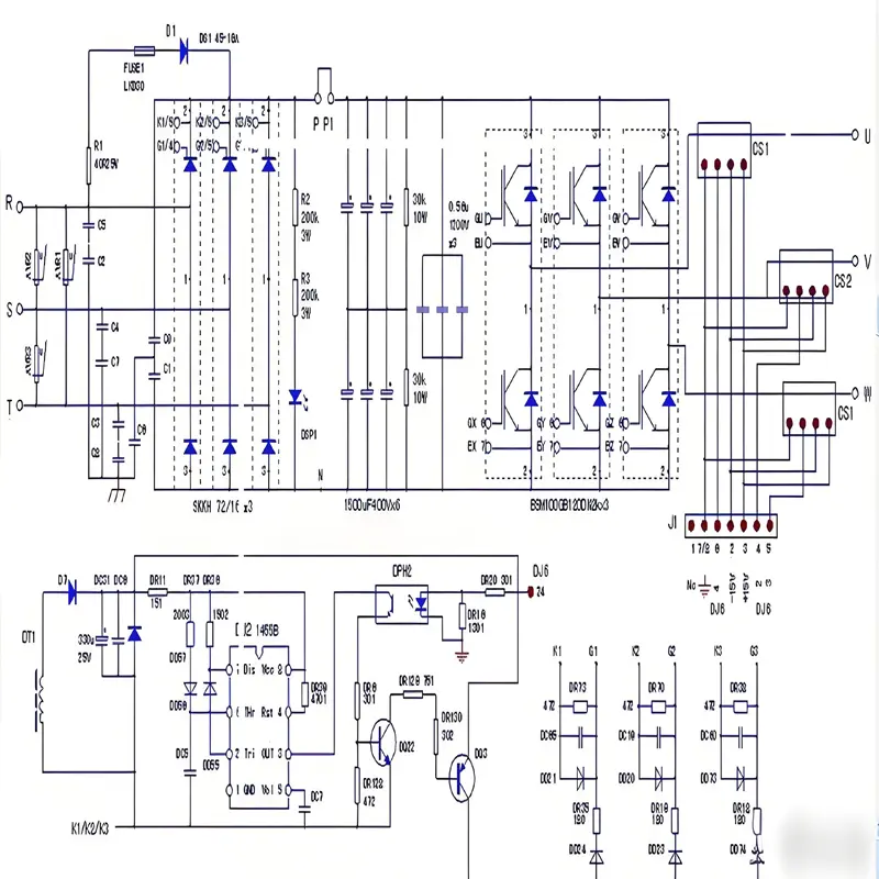
The Role of Rectifier Circuits in Inverters
In the overall architecture of a variable frequency drive (VFD), the rectifier circuit serves as the primary core component for energy conversion. Its key function is converting externally input alternating current (AC) into direct current (DC), providing a stable DC power foundation for subsequent inversion processes. Without this AC-DC conversion, inverters cannot accurately control output frequency and voltage, making rectification the first critical step in the “AC-DC-AC” conversion topology.

I. Core Functions of Rectifier Circuits in Inverters
An inverter’s operational process can be simplified into three main stages: rectification → filtering → inversion. The rectifier circuit’s functions focus on converting AC to usable DC, with two primary responsibilities:
1. AC-DC Energy Conversion (Core Task)
Inverters typically receive input from industrial AC power grids (e.g., single-phase 220V, three-phase 380V/400V). The subsequent inverter circuit (composed of power semiconductors like IGBTs) requires DC power to operate. By controlling IGBT switching, the inverter circuit “converts” DC power into AC with adjustable frequencies and voltages to drive motors.
The rectifier circuit operates on the principle of unidirectional conductivity in power diodes (or thyristors/SCRs, IGBTs), forcing current to flow in one direction only. This process “rectifies” alternating current (which cycles between positive and negative) into unidirectional direct current (known as “pulsating DC”).
2. Supplying Initial DC Power for Filtering and Inversion
The DC output from rectifiers is not perfectly smooth but contains significant fluctuations (“pulsating DC”). For example, three-phase rectification produces ripples at six times the grid frequency. This pulsating DC cannot directly power inverter circuits, as it would cause unstable output voltages and motor overheating.
Therefore, rectifier output connects directly to a filter circuit (usually large-capacity electrolytic capacitors or inductors). After filtering, a stable DC link voltage (DC-Link Voltage) is obtained. The rectifier circuit acts as the “energy inlet” for subsequent stages, determining baseline DC link voltage levels (e.g., approximately 540V for 380V three-phase input after rectification and filtering) and directly influencing inverter output power and load capacity.
II. Common Rectifier Circuit Types in Inverters
Rectifier circuits in inverters fall into two main categories based on input phase (single-phase/three-phase) and component controllability (uncontrollable/controllable), each with distinct structures and applications:
| Type | Core Components | Input Power | Characteristics | Typical Applications |
|---|---|---|---|---|
| Uncontrollable Rectifier | Power diodes | Single/three-phase | Uses diode unidirectionality for rectification without control signals. Simple structure, low cost, but non-adjustable output voltage. | Medium-small power general inverters (fans, pumps) |
| Controllable Rectifier | Thyristors (SCRs), IGBTs | Three-phase | Adjustable DC output via component conduction angle control (e.g., SCR trigger signals). Enables energy feedback. | High-power inverters, braking feedback scenarios (elevators, machine tools) |
III. Cooperative Relationships with Other Inverter Modules
Rectifier circuits work closely with filtering and inversion stages to achieve the inverter’s “voltage and frequency conversion” capabilities through this coordinated process:
- Rectification: Converts grid AC (e.g., three-phase 380V) to pulsating DC (e.g., ~540V after three-phase rectification)
- Filtering: Smooths “pulsating DC” into “stable DC” (DC link voltage, e.g., 540V) using DC bus capacitors/inductors
- Inversion: Under control unit (MCU/PLC) direction, IGBTs switch at high frequencies to invert stable DC into adjustable AC (e.g., 0-50Hz, 0-380V) for driving asynchronous or permanent magnet synchronous motors
Key Consideration: Rectifier output quality (ripple rate, voltage stability) directly impacts filtering requirements. Excessive pulsation causes filter capacitor overheating and shortened lifespan. Meanwhile, rectifier voltage range determines maximum inverter output capability (e.g., 540V DC link supports ~380V AC output).
IV. Summary
The rectifier circuit serves as the “energy conversion starting point” for inverters, with core contributions including:
- Completing fundamental “AC to DC” conversion to supply energy for the entire inverter system
- Collaborating with filtering stages to generate stable DC link voltage, ensuring reliable inverter operation
- Determining inverter capabilities (power level, voltage adjustment, energy feedback) through different circuit designs, enabling adaptation to diverse application scenarios

