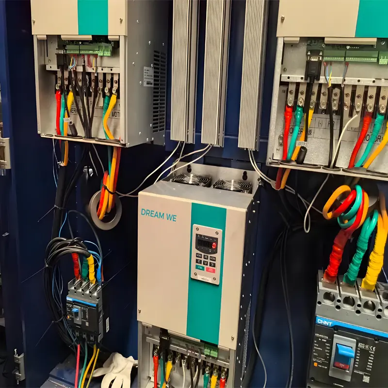
Common Causes of Frequency Converter Damage
A Variable Frequency Drive (VFD) is a critical piece of equipment in industrial automation and motor control. Its damage can lead to production disruptions and increased maintenance costs. Below are the common causes of frequency converter failure, covering electrical, environmental, operational, and maintenance factors, with specific scenario examples:

1. Electrical Factors: Overcurrent, Overvoltage, and Power Supply Irregularities
-
Abnormal input voltage
Excessively high grid voltage (e.g., voltage surges from lightning strikes or transformer malfunctions) or abnormally low voltage (e.g., due to excessive grid load) can damage internal components like rectifier bridges and electrolytic capacitors.
Example: During a thunderstorm, without a surge protector installed, high-voltage pulses can travel through power lines into the frequency converter, burning out the rectifier module. -
Output-side short circuits or ground faults
Motor winding short circuits, damaged cable insulation causing ground faults, or loose motor terminals creating arcing can trigger sudden spikes in the converter’s output current. This may overwhelm overcurrent protection mechanisms and even burn out IGBT power modules.
Example: In a humid environment, aging motor cables develop cracks, leading to a ground short. When the converter’s overload protection fails, the power unit is destroyed. -
Frequent start-stops or sudden load changes
High-frequency start-stop cycles (e.g., frequent jogging operations) can cause excessive current surges inside the converter. Sudden load increases (e.g., a jammed conveyor belt) may lead to motor stalling and subsequent overcurrent.
Example: Crane equipment that lifts and lowers frequently subjects the converter to long-term overload. Insufficient heat dissipation causes power modules to overheat and fail.
2. Environmental Factors: Temperature, Humidity, and Contamination
-
Poor heat dissipation
High ambient temperatures (exceeding the converter’s rated operating range, typically 40–50°C), faulty cooling fans, or dust-clogged heat sinks can cause internal components—especially power modules and capacitors—to overheat, leading to aging or burnout.
Example: In a textile workshop, lint accumulates over the converter’s cooling vents. During summer heatwaves, module temperatures exceed 80°C, eventually causing a breakdown. -
High humidity and corrosive gases
Environments with relative humidity above 90% can cause circuit boards to 受潮 and short-circuit. Corrosive gases (e.g., hydrogen sulfide in chemical plants or chlorine in dyeing facilities) can corrode PCBs and metal contacts, resulting in poor connections or component failure.
Example: A coastal factory without anti-corrosion measures experiences salt spray damage to internal relay contacts, interrupting control signals. -
Dust and vibration
Dust (e.g., from cement or flour) entering the converter can accumulate on circuit boards, forming conductive paths and causing short circuits. Excessive mechanical vibration (e.g., from improperly secured installations) may loosen wiring or break component solder joints.
Example: A mining converter mounted on a heavily vibrating frame suffers broken capacitor pins, cutting off the power circuit.
3. Operational Errors and Incorrect Parameter Settings
-
Unreasonable parameter configuration
Failing to set parameters (e.g., acceleration time, overcurrent protection thresholds) correctly for the motor type (asynchronous/synchronous) or load characteristics (constant/variable torque) can result in mismatched operation between the motor and converter, leading to long-term overload.
Example: Setting an overly short acceleration time for a centrifugal pump causes startup current peaks to exceed the converter’s rating, damaging modules after repeated stress. -
Improper operation
Hot-swapping connectors (e.g., control terminals or motor cables) can generate electrical sparks that damage components. Working on live equipment during maintenance (without disconnecting power) risks accidental contact with internal circuits, causing short circuits.
Example: During maintenance, a technician fails to disconnect the main power. Unplugging the speed feedback cable creates an instant induced high voltage, burning out the control board.
4. Component Aging and Quality Issues
-
Electrolytic capacitor aging
Capacitors are a vulnerable part of converters. Over time, their electrolytes dry out, reducing capacity and increasing leakage current. This impairs filtering efficiency, leading to power fluctuations or module damage. Typical lifespan is 5–8 years (halved for every 10°C increase in ambient temperature). -
Failure of wear parts (fans, relays, etc.)
Worn cooling fan bearings or oxidized relay contacts can cause heat dissipation failures or control signal irregularities, indirectly triggering converter malfunctions. -
Low-quality components or design flaws
Budget converters may use inferior IGBTs, capacitors, or other components. Poor circuit design (e.g., inadequate protection systems) reduces shock resistance, making them prone to failure under normal operating conditions.
5. External Interference and Grounding Issues
-
Electromagnetic interference (EMI)
Electromagnetic radiation from nearby welders or high-frequency equipment can disrupt the converter’s control circuit (e.g., CPU, sensors), causing program errors or misoperation. Over time, this may damage logic components. -
Poor grounding
Inadequate grounding (e.g., no dedicated ground, ground resistance >4Ω, or shared grounding with power equipment) allows stray currents to flow through the casing into circuits, burning out control boards or sensors.
Prevention Recommendations
Frequency converter damage often results from multiple overlapping factors. Preventive measures include:
- Install surge protectors and voltage regulators on the power supply side.
- Regularly clean cooling systems to maintain ambient temperatures ≤40°C and humidity ≤85%.
- Configure converter parameters strictly according to motor specifications and avoid frequent start-stops.
- Replace wear parts (capacitors, fans) periodically (every 5 years is recommended).
- Ensure proper grounding (use a dedicated ground with resistance <4Ω) and keep converters away from strong interference sources.
These steps can significantly reduce failure rates and extend the converter’s service life.

