
11/25/2025
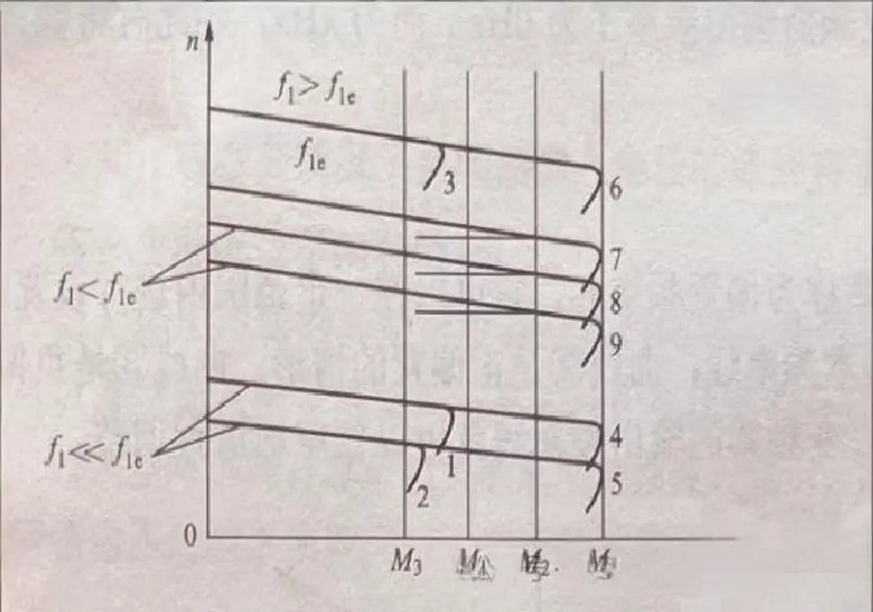
Mechanical Characteristics of Asynchronous Motors After Frequency Conversion Speed Regulation The principle of frequency conversion speed regulation is based on the formula n = 60f₁*(1-s)/p, which means that changing the stator supply frequency f₁ can alter the synchronous speed n of the motor. To maintain the motor’s maximum torque Mₘ constant during speed regulation, the stator supply voltage must be adjusted accordingly to preserve constant magnetic flux. Based on the different proportional relationships between stator voltage U₁ and stator supply frequency f₁, there are various frequency conversion speed regulation methods. Figure 1 illustrates the mechanical characteristics of asynchronous motors during frequency conversion speed regulation. (1) Proportional control method maintaining U₁/f₁ = constant: With this method, as long as U₁ and f₁ change proportionally, constant magnetic flux can be maintained, enabling frequency conversion speed regulation. However, at low frequencies, since stator impedance cannot be ignored relative to stator leakage reactance, the maximum torque Mₘ decreases as frequency decreases, and starting torque also diminishes. Curves 4 and 5 in Figure 1 represent ideal curves at low frequencies, while curves 1 and 2 show actual performance. (2) Constant magnetic flux control method maintaining maximum torque Mₘ constant: In this approach, to keep Mₘ unchanged, U₁ needs to be appropriately increased as f₁ decreases. (3) Control method maintaining constant power: When f₁ > f₁ₑ (stator power frequency), maintaining U₁/f₁ = constant would inevitably cause U₁ to exceed the stator rated voltage U₁ₑ, which is not permitted. Therefore, when f₁ > f₁ₑ, the stator voltage no longer increases but remains at U₁ = U₁ₑ, and can be approximately considered as constant power speed regulation. Curve 6 in Figure 1 is the ideal curve when f₁ > f₁ₑ, while curve 3 represents actual performance. When operating below the rated frequency f₁ₑ, the “parallel” sections of mechanical characteristic curves 7,...
Details
11/24/2025
What is the function of frequency conversion resolution? Frequency control resolution is a critical performance metric for Variable Frequency Drives (VFDs). It refers to the smallest incremental change in output frequency that the drive can precisely generate. Think of it as the finest marking on a ruler: a ruler with millimeter marks (high resolution) allows for more precise measurements than one with only centimeter marks (low resolution). For a VFD, higher resolution translates to finer control over motor speed, which is essential for advanced applications. The benefits and roles of high resolution are demonstrated in the following key areas: 1. Enables Smoother and More Precise Speed Control This is the fundamental benefit. High resolution allows for extremely fine adjustments to motor speed. Enhanced Low-Speed Stability: In applications requiring low-speed operation (e.g., textile spinning, winding, mixing), low resolution causes the motor speed to change in noticeable “steps,” leading to jerky motion or vibration. High resolution ensures the motor rotates smoothly and evenly, even at very low speeds, while maintaining stable output torque. Improved Synchronization: In multi-motor systems (e.g., conveyor lines, printing presses), high resolution ensures each motor can be minutely adjusted to maintain perfect sync. This prevents problems caused by speed differences, such as material stretching, breakage, or misalignment. 2. Improves Process Quality and Product Consistency In many manufacturing processes, motor speed is directly linked to product quality. Case Study: Winding Equipment: When winding materials like paper, film, or wire, the motor speed must be adjusted linearly as the roll diameter changes to maintain constant tension. High resolution enables seamless speed transitions, preventing defects like wrinkling, stretching, or breaks caused by sudden tension changes. Case Study: Mixers and Agitators: When processing high-viscosity fluids, even minute speed variations can impact mixing efficiency and chemical reactions. High resolution ensures process repeatability and consistent results across production batches. 3. Reduces...
Details
11/19/2025
Inverter Acceleration Time and Deceleration Time: Key Applications and Optimization The acceleration time and deceleration time of an inverter refer to the duration required for a motor to accelerate from a stopped state to a set frequency, or decelerate from a set frequency to a complete stop. Proper configuration of these two critical parameters significantly impacts motor operation smoothness, system safety, and equipment lifespan. Primary Applications 1. Industrial Manufacturing Equipment Conveyor systems: Require gradual acceleration to prevent material slippage or spillage Mixers and agitators: Prevent liquid splashing or solid particles from becoming airborne Machine tools: Ensure precision machining and operational safety 2. Pump and Fan Systems Centrifugal pumps: Mitigate water hammer effects and sudden pressure fluctuations in pipelines HVAC fan systems: Reduce mechanical stress and operational noise Compressors: Minimize motor load and energy consumption during startup 3. Material Handling Equipment Cranes and hoists: Prevent load swinging and sudden changes in cable tension Elevator systems: Ensure passenger comfort and operational safety Automated guided vehicles: Maintain stable movement and positioning accuracy 4. Production Line Conveyors Belt conveyors: Prevent product accumulation or scattering Chain conveyors: Ensure continuous and stable production flow Roller conveyors: Maintain consistent product movement speeds 5. Specialized Applications Medical equipment: Centrifuges requiring precise acceleration/deceleration control Entertainment technology: Stage lifts and rotating platforms needing smooth operation Food processing machinery: Protect product integrity from mechanical impacts Importance of Proper Acceleration and Deceleration Settings Equipment protection: Optimal acceleration/deceleration profiles reduce mechanical stress and extend equipment lifespan Energy efficiency: Properly configured ramps minimize energy consumption during startup and shutdown Process optimization: Precise speed control improves product quality and manufacturing consistency Safety enhancement: Controlled acceleration prevents accidents caused by sudden movements System reliability: Reduced mechanical wear decreases maintenance requirements and downtime Practical Considerations for Setting Adjustment When configuring acceleration and deceleration times, consider: Load characteristics...
Details
11/18/2025
Frequency Converter Anti-Stall Function: Comprehensive Guide Introduction to Motor Stall Protection The anti-stall function is a critical protective mechanism integrated into modern frequency converters (also known as variable frequency drives or VFDs) to prevent motor damage and ensure system reliability during abnormal operating conditions. This essential feature monitors motor performance in real-time and takes proactive measures to avoid potentially catastrophic stall conditions. Understanding Motor Stall Phenomenon Motor stall occurs when an electric motor’s actual operating speed falls significantly below the speed corresponding to the frequency converter’s output frequency. This mismatch typically happens when: The motor encounters excessive mechanical load resistance The load torque exceeds the motor’s rated torque capacity Acceleration/deceleration times are set too aggressively Power supply voltage fluctuates unexpectedly When a motor stalls, it continues drawing high current while producing little or no useful work, creating dangerous operating conditions. Critical Risks of Unprotected Motor Stalling 1. Thermal Damage Motor winding overheating: Stalled motors draw 5-7 times their rated current, rapidly increasing temperatures Insulation degradation: Excessive heat weakens motor insulation, leading to premature failure Component damage: Elevated temperatures damage bearings, seals, and other mechanical components 2. Electrical System Stress Overcurrent conditions: High currents can trip circuit breakers and damage power distribution systems Voltage fluctuations: Sudden current surges affect other equipment connected to the same power supply Energy waste: Stalled motors consume significant electrical energy without performing useful work 3. Operational Consequences Production downtime: Unexpected motor failures disrupt manufacturing processes Equipment damage: Mechanical shock from sudden stalls can damage connected machinery Safety hazards: Stalling in critical applications like elevators or conveyors poses safety risks How Anti-Stall Protection Works The anti-stall function continuously monitors key motor parameters and implements corrective actions when stall conditions are detected: Real-time parameter monitoring: The system tracks motor current, torque, speed, and power consumption Threshold detection: When parameters exceed predefined...
Details
11/17/2025
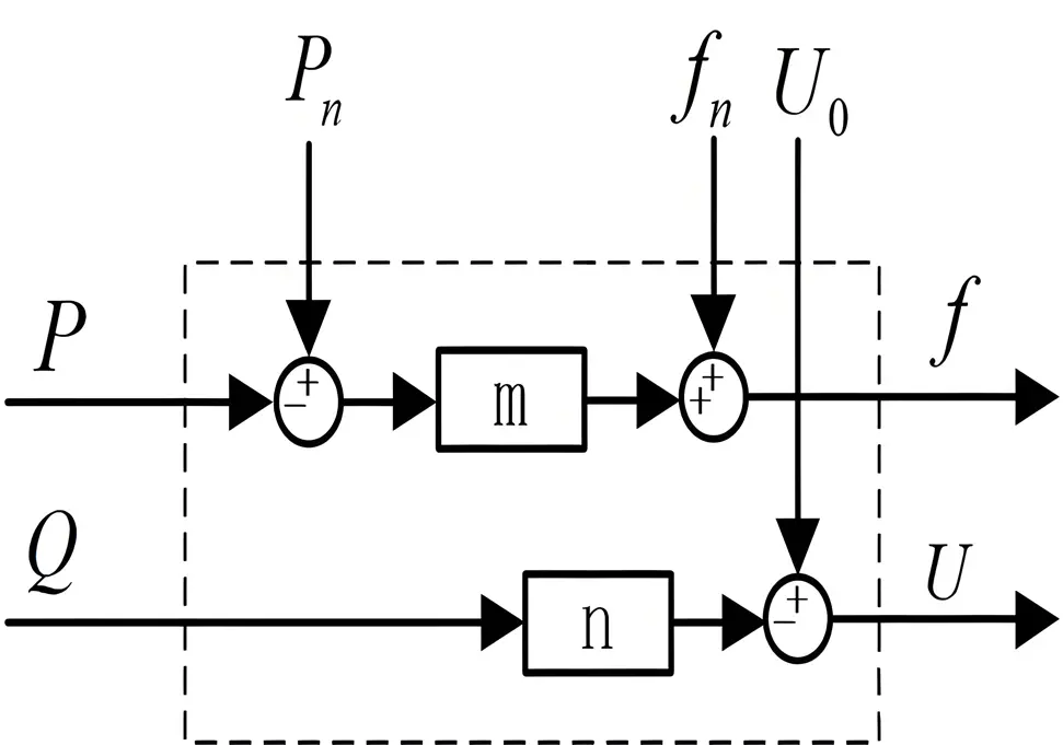
Droop Control for Frequency Converters (Inverters) – A Plain-Language Guide 1. What it is Droop control imitates the natural speed-droop characteristic of a traditional synchronous generator. It lets several motors or inverters work in parallel without any data cable between them, automatically sharing the load. 2. The basic idea (one-sentence version) “Whoever works harder runs a tiny bit slower; whoever works less runs a tiny bit faster.” 3. How it works in plain words When a motor suddenly sees more load, its output frequency drops a little. The other motors feel that micro-slow-down and pick up the extra kilowatts. When the load decreases, the process reverses. No master controller is required; each unit decides for itself. 4. Key equation (frequency droop) f = f₀ – kₚ · P f: actual output frequency f₀: no-load frequency set-point kₚ: frequency-droop coefficient (Hz per kW) P: active power the unit is delivering 5. Where it is used Multi-motor conveyor belts – keeps every motor equally loaded Gantry crane long-travel drives – keeps both sides synchronized so the crane does not skew Micro-grids or battery inverters – keeps many small sources in parallel without communication 6. Pros and cons Advantages No communication wires needed; simple and rugged Natural redundancy—if one unit trips, the others absorb its share Behaves like a real generator, so power-system operators understand it Drawbacks Steady-state error: frequency and voltage move away from the nominal value Load-sharing accuracy depends on cable impedance and calibration Slower dynamic response; may need supplementary control for fast transients 7. One-line takeaway Droop control turns a group of frequency converters into self-balancing teammates: they automatically share the burden, running a hair slower when they shoulder more and a hair faster when they lighten up.
Details
11/14/2025
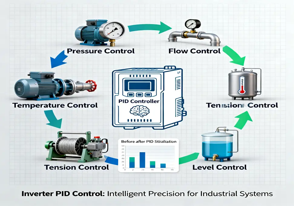
What are the application scenarios of PID control for frequency converters? Introduction Inverter PID control is a cornerstone of modern industrial automation. But what exactly is it, and where is it used? Simply put, an inverter regulates a motor’s speed, while the PID controller acts as its “intelligent brain.” This brain continuously calculates the difference between a desired setpoint and a measured feedback value from a sensor. It then dynamically adjusts the motor speed based on Proportional (P), Integral (I), and Derivative (D) actions to maintain a physical variable—like pressure or temperature—at a stable target level. This article explores the most common and effective application scenarios for inverter PID control. 1. Pressure Control This is one of the most classic applications, ideal for maintaining constant pressure in pipelines or vessels. Constant Pressure Water Supply: How It Works: A pressure transmitter installed on the water network provides real-time feedback to the inverter. The PID logic adjusts the pump motor’s speed to maintain the set pressure. When water demand increases and pressure drops, the PID increases pump speed. When demand falls, it reduces speed. Key Benefits: This system replaces inefficient water towers, ensures stable water pressure, and offers significant energy savings (typically 20-40%). It also minimizes pressure shocks to the pipeline caused by frequent pump starts and stops. Air Compressor Control: How It Works: Similarly, the inverter uses feedback from a pressure sensor at the air tank’s output. The PID controller adjusts the compressor motor’s speed to deliver a stable air pressure. Key Benefits: It prevents the compressor from constantly loading and unloading, reducing energy consumption and wear, thereby extending equipment life. 2. Flow Control This application ensures a consistent flow rate of liquids or gasses in a process. How It Works: A flow meter (e.g., electromagnetic or turbine) measures the instantaneous flow. The inverter’s PID controller uses this data to adjust the...
Details
11/14/2025
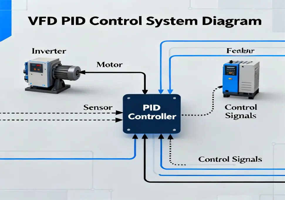
VFD PID Control: A Comprehensive Guide to Proportional-Integral-Derivative Control in Variable Frequency Drives 1. Introduction to PID Control 1.1 What is PID Control? PID (Proportional-Integral-Derivative) control is a widely used feedback control algorithm in industrial automation systems. It is designed to maintain a process variable at a desired setpoint by calculating and applying a correction based on proportional, integral, and derivative terms. Core Principle: PID control continuously calculates an error value as the difference between a desired setpoint (SP) and a measured process variable (PV), then applies a correction based on three terms to minimize this error. 1.2 Importance of PID Control in Industrial Automation PID control plays a crucial role in modern industrial automation for several reasons: Precision Control: Maintains process variables at desired setpoints with high accuracy Reduces variations and deviations in production processes Improves product quality and consistency Versatility: Suitable for a wide range of industrial applications Works with various types of sensors and actuators Adaptable to different process dynamics Robustness: Performs well under varying load conditions Tolerates changes in system parameters Provides stable operation across different operating points 1.3 PID Control vs Other Control Methods Control Method Complexity Precision Tuning Difficulty Application Suitability PID Control Medium High Medium Most industrial processes On-Off Control Low Low None Simple temperature control Proportional Control Low Medium Low Simple level control Fuzzy Logic Control High High High Complex nonlinear processes Model Predictive Control Very High Very High Very High Advanced process control 2. PID Control Fundamentals 2.1 PID Controller Structure A PID controller consists of three main components that work together to calculate the control output: ** 1. Proportional (P) Term Responds to the current error Output is proportional to the magnitude of the error Provides immediate correction action 2. Integral (I) Term Responds to the accumulated error over time...
Details
11/14/2025
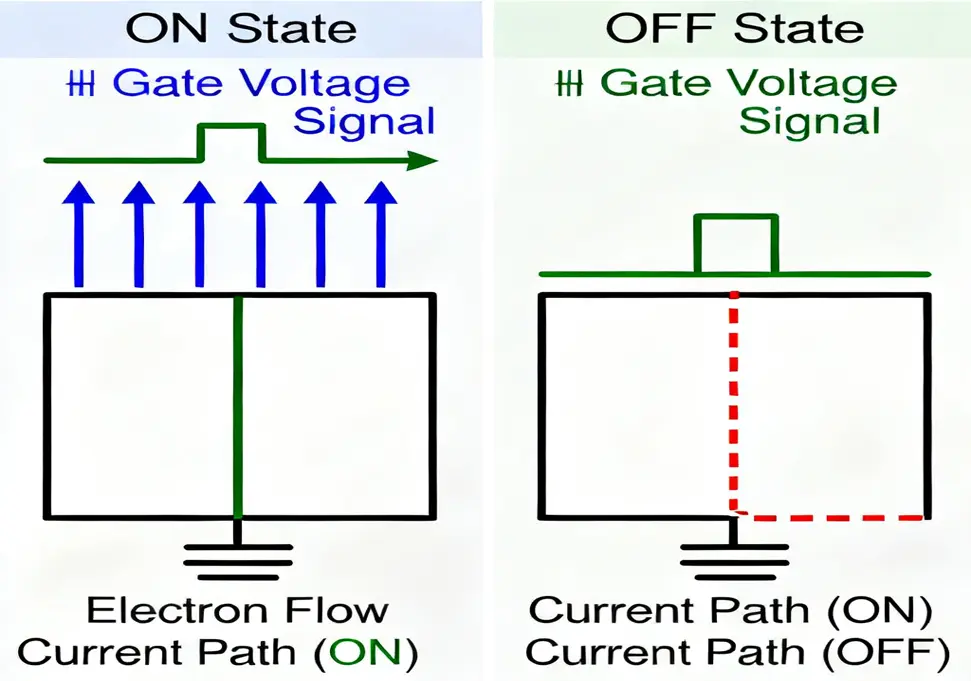
IGBT Technology in Inverters: A Comprehensive Guide to Insulated Gate Bipolar Transistors 1. Introduction to IGBT Technology 1.1 What is an IGBT? An Insulated Gate Bipolar Transistor (IGBT) is a high-performance power semiconductor device that combines the best features of two widely used electronic components: the MOSFET (Metal-Oxide-Semiconductor Field-Effect Transistor) and the BJT (Bipolar Junction Transistor). This hybrid technology creates a versatile switching device capable of handling high voltages and large currents with exceptional efficiency. Key Definition: IGBT is a voltage-controlled power semiconductor device designed for high-power applications, serving as a fast electronic switch that can be precisely controlled to turn on and off thousands of times per second. 1.2 The Importance of IGBT in Modern Electronics IGBT technology has revolutionized power electronics by enabling: Efficient Power Conversion: Significantly reducing energy losses in electrical systems Precise Control: Allowing accurate regulation of power flow and motor speed Compact Design: Enabling smaller, lighter power electronic equipment Cost-Effectiveness: Providing superior performance at competitive pricing In industrial automation, IGBTs are often referred to as the “CPU of power electronics” due to their central role in controlling and converting electrical energy. 1.3 IGBT vs Traditional Power Devices Device Type Control Method Key Advantages Key Disadvantages Typical Applications IGBT Voltage-controlled High input impedance, low conduction loss, fast switching Higher cost than BJT Inverters, motor drives, power supplies MOSFET Voltage-controlled Extremely fast switching, simple gate drive High conduction loss at high voltages Low-power applications, consumer electronics BJT Current-controlled Low conduction loss, mature technology Complex drive circuit, slow switching Legacy systems, low-frequency applications GTO Current-controlled High power handling capability Complex drive requirements, slow switching High-voltage DC transmission 2. IGBT Structure and Working Principle 2.1 Basic IGBT Structure An IGBT consists of multiple layers of semiconductor materials arranged in a specific configuration to achieve its unique performance characteristics. The...
Details
11/13/2025
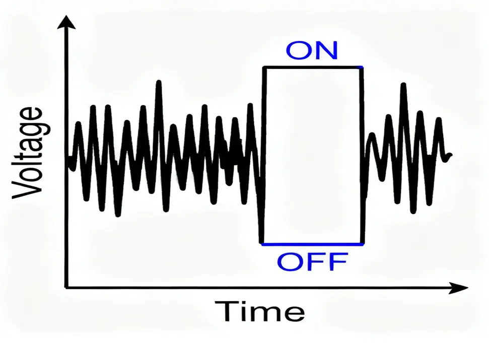
Inverter Digital Input/Output: A Comprehensive Guide to Switching Quantity in Industrial Automation 1. Basic Concepts of Switching Quantity 1.1 What is Switching Quantity Switching quantity, also known as discrete quantity or digital quantity, refers to electrical signals that have only two distinct states: ON/OFF, open/closed, or binary 0/1. In industrial automation, switching quantity forms the foundation of logic control systems, providing simple yet powerful mechanisms to control and monitor equipment status in manufacturing and process industries. Key Characteristics of Switching Quantity: Binary nature: Only two possible states exist Instantaneous transition: Changes occur abruptly between states Stable states: Remains in one state until triggered to change Easy to process: Simple for digital systems to interpret and generate ** 1.2 Common Switching Quantity Signals In industrial control systems, common switching quantity signals include: Input Signals: Start/Stop buttons: Manual control of equipment operation Limit switches: Detecting mechanical positions Emergency stop signals: Safety interlock mechanisms Selector switches: Mode selection and configuration Proximity sensors: Non-contact object detection Pressure switches: Pressure threshold detection Temperature switches: Temperature limit protection Output Signals: Contactor coils: Controlling power circuits Indicator lights: Status visualization Solenoid valves: Fluid control Relay coils: Circuit switching Alarm devices: Audible/visual alerts 1.3 Switching Quantity in Daily Life Switching quantity is ubiquitous in our daily lives: Light switches: Turning lights on and off Power buttons: Activating electronic devices Doorbells: Pushbutton activation Thermostat controls: Heating/cooling system activation Car ignition: Engine start/stop control These everyday examples demonstrate the fundamental simplicity and effectiveness of switching quantity control. 2. Inverter Digital Input (DI) 2.1 Definition of Digital Input Digital Input (DI) terminals on variable frequency drives (VFDs) serve as the primary interface for receiving external switching signals from various control devices. These inputs enable operators and automated control systems to command the inverter to perform specific functions through simple yet reliable...
Details

11/13/2025
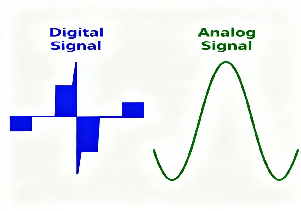
Inverter Analog Input/Output: A Complete Technical Guide for Industrial Automation 1. Basic Concepts of Analog Quantity 1.1 What is Analog Quantity Analog signals refer to continuously varying electrical quantities that can take any value within a specified range. Unlike digital signals, which only have discrete values (typically 0 or 1), analog signals provide smooth, continuous representation of real-world physical phenomena such as temperature, pressure, and speed. Characteristics of Analog Quantity: Continuity: Signals change smoothly without discrete steps Precision: Can represent small changes in physical quantities Real-world representation: Ideal for measuring natural phenomena Infinite resolution: Theoretically can represent any value within range 1.2 Analog Quantity in Daily Life In our daily lives, we encounter numerous examples of analog quantities: Temperature: Changes continuously throughout the day Sound volume: Can be adjusted smoothly up or down Light intensity: Varies gradually from dark to bright Water flow: Can be adjusted to any level between fully open and closed These natural phenomena change continuously, making analog signals the perfect way to represent them in electronic systems. 1.3 Standard Analog Signals In industrial automation, standard analog signal ranges have been established for consistency: Voltage Signals: 0-10V: Most common voltage range for analog inputs 0-5V: Used in some legacy systems ±10V: For applications requiring both positive and negative values Current Signals: 0-20mA: Basic current loop standard 4-20mA: Most widely used (provides live zero for fault detection) 0-10mA: Older standard, less common today The 4-20mA current loop standard is particularly popular in industrial applications due to several key advantages: Fault detection capability: The 4mA “live zero” allows detection of open-circuit faults Superior noise immunity: Current signals are less susceptible to electromagnetic interference than voltage signals Extended transmission distances: Can reliably transmit signals over hundreds of meters Simplified wiring: Requires only two wires for both power and signal transmission...
Details
11/13/2025
Inverter Digital Quantity: A Comprehensive Technical Guide 1. Basic Concepts of Digital Quantity 1.1 What is Digital Quantity Digital quantity, also known as discrete quantity or switching quantity, refers to signals that are discrete in both time and amplitude. In industrial automation, digital signals are typically represented using binary values (0 and 1) to indicate two distinct states. Characteristics of Digital Quantity: Discreteness: The signal has only two states with no intermediate transition state Strong anti-interference ability: Digital signals are not easily affected by electromagnetic interference High precision: Digital signal transmission and processing have high precision Easy to process: Suitable for processing by computers and microprocessors 1.2 Digital Quantity in Daily Life In daily life, we often encounter examples of digital quantities: Light switch: Either on (bright) or off (dark) Water tap: Either open (with water) or closed (without water) Doorbell button: Pressed (with signal) or released (without signal) These devices all have only two states, no intermediate states, which is the typical characteristic of digital quantities. 2. Inverter Digital Input (DI) 2.1 Definition of Digital Input Digital Input (DI) serves as the interface through which inverters receive external switching signals. These signals typically originate from external devices including buttons, switches, sensors, or Programmable Logic Controllers (PLCs). 2.2 Digital Input Terminals Inverters usually provide multiple digital input terminals, with common identifiers including: DI1, DI2, DI3… (Digital Input) X0, X1, X2… S0, S1, S2… MI1, MI2, MI3… (Multi-function Input) ** 2.3 Functions of Digital Input Digital input terminals can achieve multiple functions through parameter settings: Basic Control Functions: Start/Stop Control: Control the start and stop of the inverter through external buttons Forward/Reverse Control: Control the forward and reverse rotation of the motor through different input terminals Jog Control: Realize jog operation of the motor Speed Control Functions: Multi-speed Control: Realize preset...
Details
11/12/2025
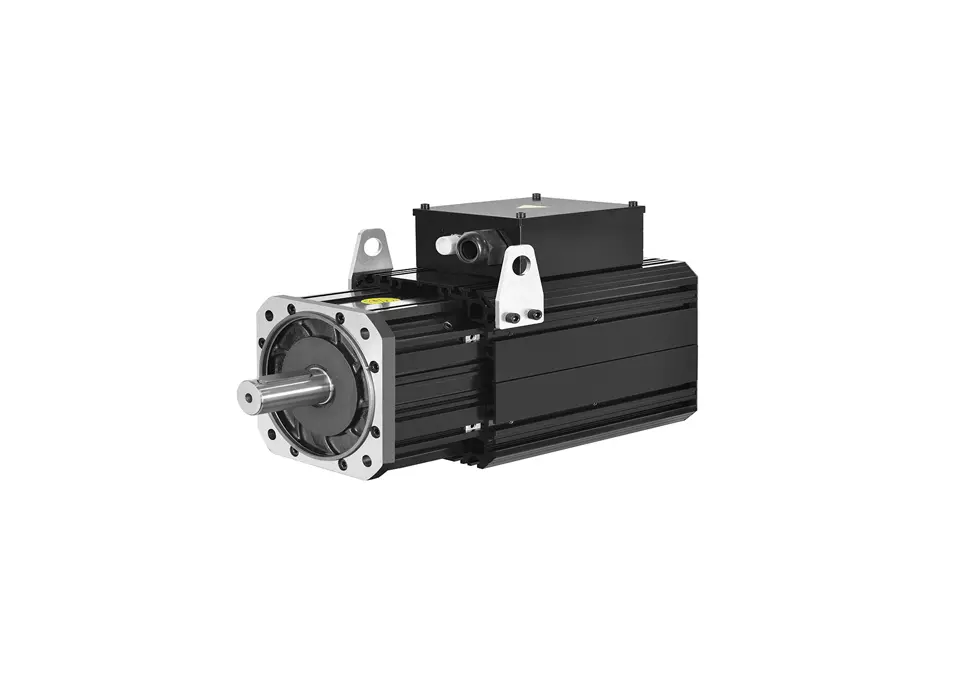
Complete Guide to Permanent Magnet Synchronous Motors (PMSM): Working Principles, Applications & Advantages Permanent Magnet Synchronous Motors (PMSM) represent advanced motor technology that offers exceptional efficiency and performance advantages over traditional motor designs. By utilizing permanent magnets to create the excitation field, PMSMs have revolutionized various industries from automotive to renewable energy. This comprehensive guide explores the technology behind PMSMs, their working principles, performance characteristics, and diverse applications. Understanding PMSM Working Principles and Operation The operational principle of PMSMs is based on fundamental electromagnetic principles and magnetic field interactions: Stator Winding Configuration Three-phase windings strategically distributed in stator core slots When energized with three-phase alternating current, creates a rotating magnetic field The rotating field speed is determined by the power frequency and number of pole pairs Field rotation follows a precise sinusoidal pattern for optimal performance Rotor Permanent Magnet System High-strength permanent magnets embedded or surface-mounted on the rotor Creates a constant magnetic field without external excitation requirements Rare-earth magnet materials provide superior magnetic properties Magnet arrangement designed to maximize torque production Synchronous Operation Mechanism Rotor magnetic field synchronizes with stator rotating magnetic field Maintains precise speed relationship: n = 60f/p (speed = 60 × frequency/pole pairs) No slip between rotor and stator fields during steady-state operation Requires proper synchronization during startup to avoid damage Electromagnetic Energy Conversion Torque generation through interaction between stator and rotor magnetic fields Efficient conversion of electrical energy to mechanical energy Power transfer occurs through electromagnetic coupling Minimal energy losses compared to asynchronous motor designs Comprehensive PMSM Structural Analysis Advanced Stator Design Features Core Construction Technology High-grade silicon steel laminations to minimize core losses Precisely punched slots for optimal winding placement Back iron design optimized for magnetic flux distribution Cooling channels integrated into core structure for thermal management Winding Configuration Options Distributed winding for sinusoidal...
Details