
11/12/2025
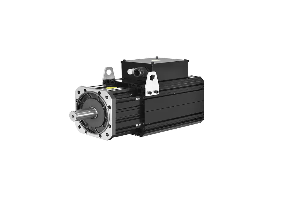
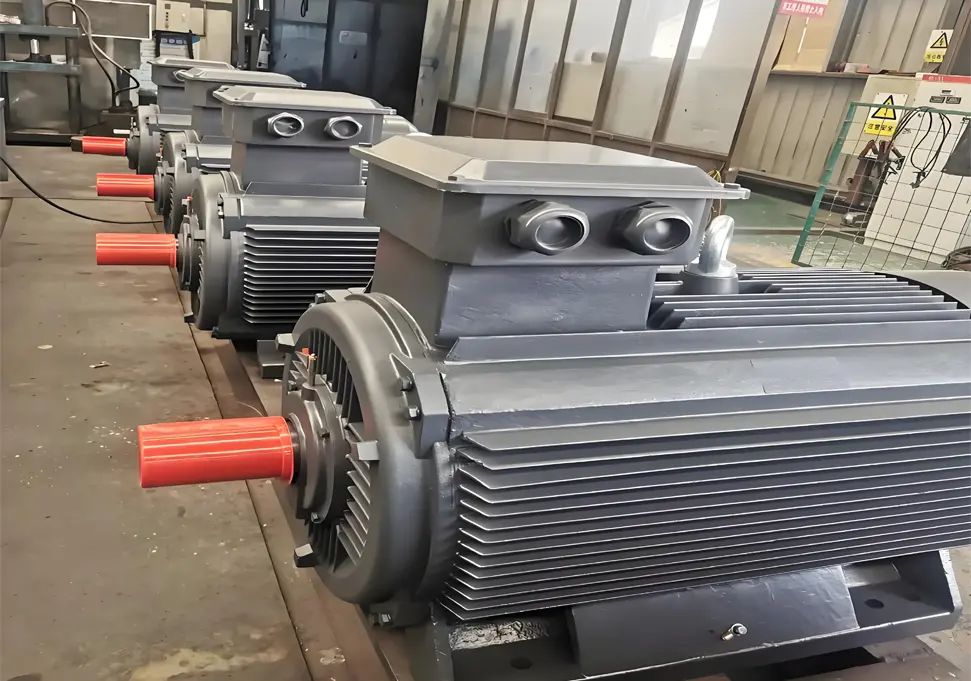
Complete Guide to Permanent Magnet Synchronous Motors (PMSM): Working Principles, Applications & Advantages Permanent Magnet Synchronous Motors (PMSM) represent advanced motor technology that offers exceptional efficiency and performance advantages over traditional motor designs. By utilizing permanent magnets to create the excitation field, PMSMs have revolutionized various industries from automotive to renewable energy. This comprehensive guide explores the technology behind PMSMs, their working principles, performance characteristics, and diverse applications. Understanding PMSM Working Principles and Operation The operational principle of PMSMs is based on fundamental electromagnetic principles and magnetic field interactions: Stator Winding Configuration Three-phase windings strategically distributed in stator core slots When energized with three-phase alternating current, creates a rotating magnetic field The rotating field speed is determined by the power frequency and number of pole pairs Field rotation follows a precise sinusoidal pattern for optimal performance Rotor Permanent Magnet System High-strength permanent magnets embedded or surface-mounted on the rotor Creates a constant magnetic field without external excitation requirements Rare-earth magnet materials provide superior magnetic properties Magnet arrangement designed to maximize torque production Synchronous Operation Mechanism Rotor magnetic field synchronizes with stator rotating magnetic field Maintains precise speed relationship: n = 60f/p (speed = 60 × frequency/pole pairs) No slip between rotor and stator fields during steady-state operation Requires proper synchronization during startup to avoid damage Electromagnetic Energy Conversion Torque generation through interaction between stator and rotor magnetic fields Efficient conversion of electrical energy to mechanical energy Power transfer occurs through electromagnetic coupling Minimal energy losses compared to asynchronous motor designs Comprehensive PMSM Structural Analysis Advanced Stator Design Features Core Construction Technology High-grade silicon steel laminations to minimize core losses Precisely punched slots for optimal winding placement Back iron design optimized for magnetic flux distribution Cooling channels integrated into core structure for thermal management Winding Configuration Options Distributed winding for sinusoidal...
Details
11/12/2025
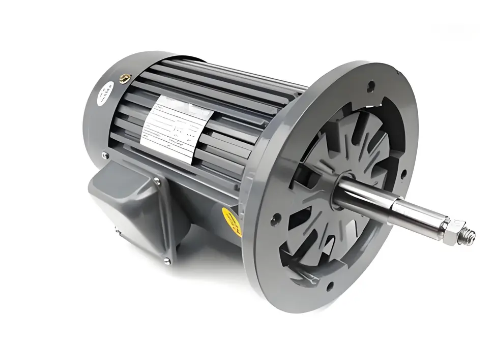
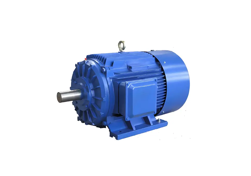
Ultimate Guide: How to Identify Brushless vs Brushed Motors When working with electric motors, being able to distinguish between brushless and brushed technologies is essential for proper maintenance, repair, and replacement decisions. This comprehensive guide outlines proven methods to identify motor types through visual inspection, structural analysis, and operational testing. Visual Inspection Techniques for Motor Identification Examining Motor End Construction Key Brushed Motor Features Distinctive metal or plastic end caps designed to house the brushes and commutator assembly Access panels or removable sections for brush inspection and replacement Longer axial length to accommodate the commutator mechanism Visible brush wiring on smaller motor models Identifying Brushless Motor Designs Smooth, uniform end caps without protrusions or access openings Compact overall dimensions with shorter axial profile Integrated Hall sensor connectors on the motor housing Heat sink features on the exterior casing for thermal management Analyzing Terminal Connections Brushed Motor Wiring Patterns Typically feature only two primary power terminals (positive and negative) May include additional terminals for speed control or braking functions Minimal terminal count, generally fewer than 4 connections total Simple wiring configuration without complex connectors Brushless Motor Connection Characteristics Three main power phase terminals (usually labeled U, V, W or A, B, C) Multiple signal terminals (5-8) for Hall effect sensors Higher terminal count, typically 8-12 connections Complex multi-pin connectors rather than individual terminals Structural Analysis Methods Size and Weight Comparison Brushed Motor Physical Traits Larger overall dimensions for equivalent power ratings Heavier rotor assembly containing windings and commutator Higher rotational inertia affecting performance characteristics Bulkier construction with less efficient use of space Brushless Motor Design Advantages Superior power density with smaller footprint for same power output Lighter rotor assembly utilizing permanent magnet technology Lower rotational inertia enabling faster response times Compact, space-efficient construction Thermal Management Features Brushed Motor Cooling Systems Primarily...
Details
11/12/2025
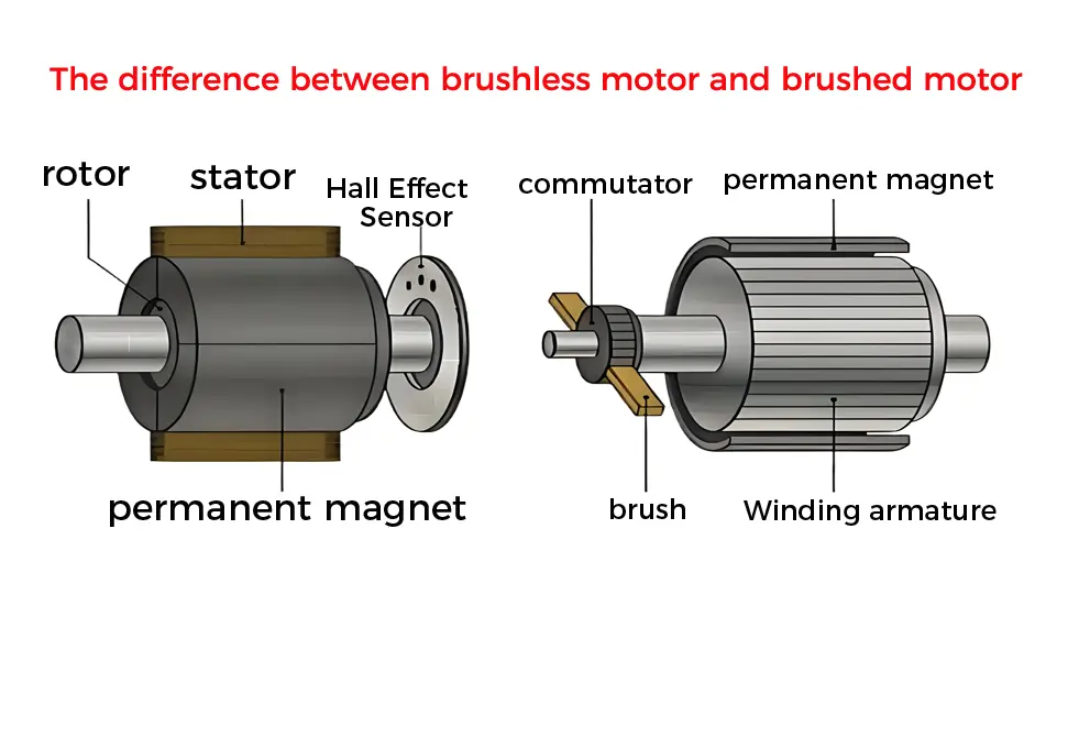
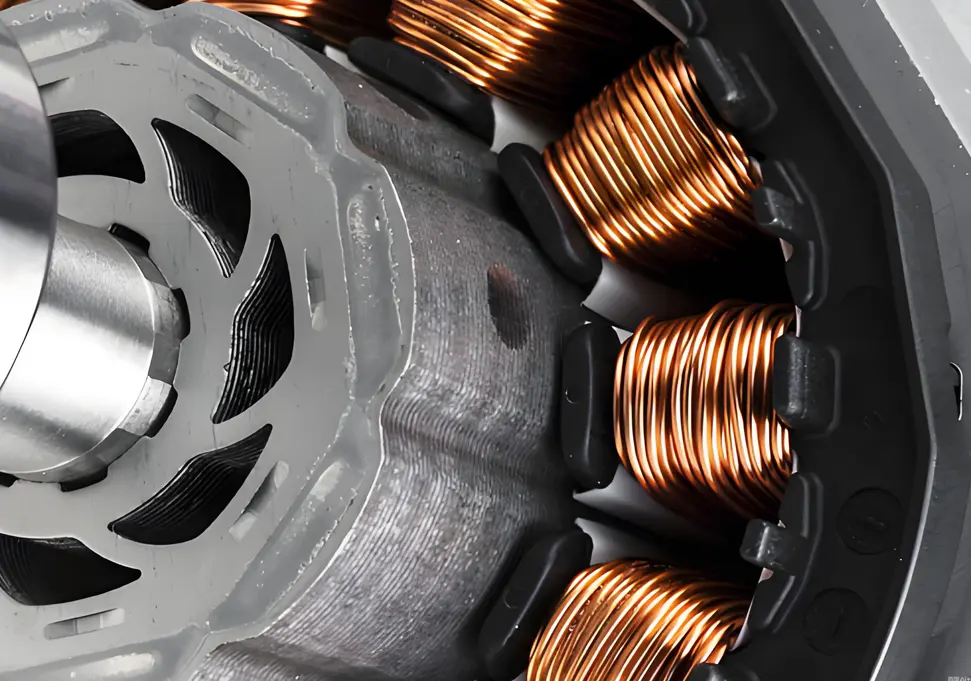
Brushless vs Brushed Motors: Comprehensive Comparison Guide When it comes to electric motor technology, understanding the fundamental differences between brushless and brushed motors is essential for making informed decisions in product design, equipment selection, and system optimization. These two motor technologies offer distinct advantages and disadvantages that significantly impact performance, efficiency, maintenance requirements, and overall cost of ownership. Fundamental Structural Differences Brushed Motor Construction Key Components Incorporates physical carbon brushes and a mechanical commutator Rotor assembly contains wire windings connected to the commutator Stator typically consists of permanent magnets or field windings Brush holders maintain contact pressure between brushes and commutator Brushless Motor Construction Modern Design Features Eliminates physical brushes and mechanical commutators Rotor assembly usually features high-strength permanent magnets Stator contains multiple wire windings arranged in a specific pattern Requires electronic speed controller (ESC) for operation Operational Principles Explained Brushed Motor Functionality Current Flow Process Electrical current travels through brushes into the commutator Commutator segments distribute current to appropriate rotor windings Electromagnetic fields are created in the rotor windings Interaction between rotor and stator magnetic fields produces rotational torque Commutator mechanically reverses current direction as rotor turns Brushless Motor Functionality Electronic Commutation System Position sensors detect rotor orientation (hall effect sensors or sensorless designs) Electronic speed controller processes sensor data ESC sequentially energizes stator windings in optimal sequence Rotating magnetic field is created in the stator Rotor permanent magnets follow the rotating magnetic field Performance Characteristics Comparison Performance Metric Brushed Motors Brushless Motors Energy Efficiency 60-75% typical 85-95% typical Speed Regulation Basic control capability Precise speed control Starting Torque High initial torque Moderate starting torque Maximum RPM Limited by commutator Higher RPM capability Operational Lifespan 1,000-3,000 hours 10,000-20,000+ hours Maintenance Requirements Regular brush replacement Minimal maintenance Noise Production Noticeable operational noise Quiet operation EMI Generation Significant interference Minimal electromagnetic...
Details
11/11/2025
Comprehensive Guide to Motor Shaft Extension Protection Requirements Motor shaft extensions serve as critical power transmission components in industrial machinery, but they also present significant safety hazards due to their rotating nature. Proper protection of these components is essential for ensuring workplace safety, preventing accidents, and maintaining equipment reliability. This comprehensive guide outlines the key requirements for effective motor shaft extension protection systems. Essential Safety Requirements for Motor Shaft Protection Protection Coverage Specifications Complete Enclosure Requirements Protective devices must fully enclose all rotating elements including shaft extensions, keyways, shaft ends, and couplings Total coverage eliminates exposure of moving parts that could cause injury Safety distance calculations must account for maximum shaft deflection during operation Protection must extend beyond the immediate shaft area to include associated rotating components Structural Integrity Standards Protective barriers must withstand minimum impact forces as specified in ISO 13857 Materials must maintain structural integrity under expected operating conditions Design must prevent accidental dislodgement during machine operation Load-bearing capacity should exceed anticipated forces from normal operation and maintenance activities Access Prevention Measures Physical barriers must prevent finger, hand, or tool access to hazardous areas openings or gaps must not exceed 8mm for finger protection Perimeter protection should extend to prevent reaching around, under, or over the guard Design must account for human factors engineering principles to prevent unintentional access Protective Device Classification and Selection Fixed Protective Systems Permanent Barrier Solutions Bolted or welded enclosures requiring tools for removal Ideal for applications with minimal maintenance requirements Materials selection based on environmental conditions and durability needs Design should facilitate visual inspection without removal Adjustable and Removable Protection Quick-Access Design Features Hinged or sliding mechanisms for maintenance access Quick-release fasteners that maintain security during operation Position indicators to confirm proper closure Interlocking capabilities to prevent operation when open Interlocking Protection Systems...
Details
11/11/2025
Key Factors Affecting Electric Motor Stability and Performance Motor stability is a critical factor that directly impacts equipment performance, operational efficiency, and service life in industrial applications. Understanding the various elements that influence motor stability is essential for maintenance professionals, engineers, and facility managers. In this comprehensive guide, we explore the primary factors affecting motor stability and provide insights into optimizing motor performance. Electrical System Factors Power Supply Quality Voltage fluctuations and instability directly impact motor output power consistency Frequency variations significantly influence motor speed regulation and stability Harmonic distortion in power supplies causes additional losses, heating, and premature wear Three-phase voltage imbalance leads to motor overheating, torque ripple, and reduced efficiency Motor Design Parameters Winding configuration and distribution affect magnetic field uniformity and torque production Number of poles and stator design influence rotational speed stability and performance characteristics Insulation class rating determines the motor’s ability to withstand temperature variations Rotor construction impacts starting torque, running efficiency, and overall operational stability Control System Performance Variable Frequency Drive (VFD) technology and control algorithms directly affect speed regulation Feedback system precision and response time influence dynamic performance Control parameter optimization is critical for achieving desired performance characteristics Protection system design prevents damage from electrical faults and abnormal operating conditions Mechanical System Factors Load Characteristics and Requirements Load type classification (constant torque, variable torque, constant power) Load variation rates and impact load handling capability Starting and braking torque requirements during transient operations Load-motor matching for optimal performance and efficiency Installation and Alignment Quality Precise motor-to-load alignment minimizes vibration and premature wear Proper bearing installation and lubrication ensure smooth operation Foundation stiffness and vibration isolation measures reduce external influences Coupling selection and installation affect torque transmission efficiency Mechanical Resonance Considerations System natural frequency identification and management Critical speed avoidance through proper design and operation...
Details
11/11/2025
Why Motor Inverters Need Skip Frequency Settings: A Comprehensive Guide If you work with electric motors and variable frequency drives (VFDs), you may have encountered the term “skip frequencies.” But why are these settings important, and how do they affect motor performance? In this article, we’ll explore the science behind skip frequencies and why they’re essential for optimal motor operation. Understanding Skip Frequencies in Motor Control Skip frequencies, also known as avoidance frequencies or jump frequencies, are specific points within an inverter’s operating range that the system is programmed to bypass. When a motor accelerates or decelerates, the VFD automatically skips these predetermined frequencies rather than operating at them continuously. The Critical Role of Skip Frequencies Preventing Mechanical Resonance The primary reason for implementing skip frequency settings is to avoid a phenomenon known as mechanical resonance. Every motor and the equipment it powers has a unique natural vibration frequency determined by factors like: Physical dimensions and material properties Mounting configuration Load characteristics System rigidity When a motor operates at or near this natural frequency, resonance occurs, creating a feedback loop that amplifies vibrations throughout the system. Consequences of Uncontrolled Resonance Without proper skip frequency settings, resonance can lead to numerous problems: Excessive noise pollution in the workplace Accelerated wear on bearings, gears, and other mechanical components Premature equipment failure and increased maintenance costs Reduced precision in manufacturing processes Safety hazards from excessive vibration Potential damage to structural components Equipment-Specific Applications Certain types of machinery are particularly susceptible to resonance issues and therefore benefit greatly from skip frequency settings: Precision machine tools requiring tight tolerances Elevators and escalators where smooth operation is critical Centrifuges and high-speed rotating equipment Industrial fans and blowers Pumps and compressors Conveyor systems and material handling equipment Implementing Effective Skip Frequency Settings Identifying Critical Frequencies To establish...
Details
11/04/2025
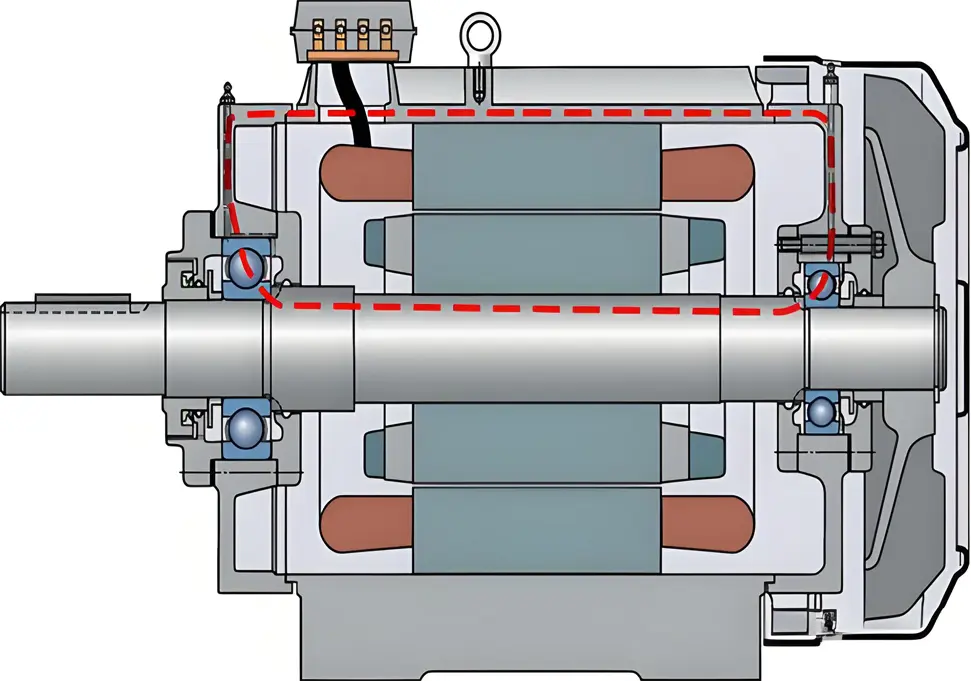
Shaft Current in Electric Motors: Causes, Effects, and Prevention Strategies Introduction Shaft current in electric motors is a critical issue that can lead to premature equipment failure, increased maintenance costs, and unexpected downtime. This comprehensive guide explores the various causes of shaft current, its detrimental effects on motor performance, and effective prevention strategies to ensure reliable and efficient motor operation. Understanding Shaft Current Shaft current refers to the flow of electrical current along the rotating shaft of an electric motor. This current typically travels from one end of the shaft to the other, or between the shaft and other motor components such as bearings and the motor frame. While motors are designed to be electrically neutral, various factors can create potential differences that initiate this unwanted current flow. Primary Causes of Shaft Current 1. Magnetic Circuit Asymmetry Stator core irregularities: Manufacturing imperfections in stator core laminations Rotor misalignment: Eccentricity between rotor and stator creating uneven air gaps Core saturation issues: Localized magnetic saturation due to design flaws or overloading Winding faults: Short circuits or ground faults causing magnetic field distortions 2. Electrostatic Induction Triboelectric charging: Friction between shaft and bearings generating static electricity Belt-driven systems: Charge generation through belt-pulley friction Oil film breakdown: High-speed operation causing lubricant film breakdown Environmental conditions: Low humidity environments promoting static accumulation 3. Electromagnetic Induction Effects Variable frequency drive (VFD) harmonics: High-frequency components inducing shaft voltages Flux cutting: Rotating shaft cutting through magnetic fields Capacitive coupling: Voltage transfer between windings and shaft Common-mode voltages: Voltage imbalances in three-phase systems 4. Grounding System Problems Improper grounding design: Inadequate or inconsistent grounding practices Multiple grounding points: Different potential levels at various grounding locations Ground loop formation: Current circulation within grounding systems Ground potential differences: Voltage variations between different earth points 5. Power Quality Issues Voltage harmonics: Non-sinusoidal...
Details