
08/26/2025
What Do Solar Panels Do? Solar panels are devices designed to convert sunlight into usable electricity—a process that leverages renewable energy to power homes, businesses, and even off-grid systems, reducing reliance on fossil fuels and lowering carbon footprints. Here’s a breakdown of their core function, working mechanism, and key roles: 1. Core Function: Turn Sunlight into Electricity At their heart, solar panels capture sunlight (specifically, the photons in sunlight) and convert this light energy into direct current (DC) electricity—the raw form of electricity that needs further processing to power most appliances. Unlike non-renewable energy sources (e.g., coal, natural gas), they generate electricity without emitting greenhouse gases, making them a clean energy solution. 2. How They Work: The Photovoltaic Effect Solar panels are made of photovoltaic (PV) cells (typically silicon-based, the most common and efficient material). The process unfolds in 3 simple steps: Absorb Sunlight: PV cells have a protective top layer that lets sunlight pass through and reach a semiconductor material (e.g., silicon). When photons hit the semiconductor, they knock electrons loose from their atomic bonds. Generate an Electric Current: The PV cell’s design (with positive and negative layers) creates an electric field that pushes these loose electrons in a single direction, forming a steady flow of DC electricity. Convert to Usable AC Electricity: Most homes and devices run on alternating current (AC) electricity, so the DC power from solar panels is sent to a solar inverter (a key system component) to be converted to AC. After conversion, the electricity can be used immediately, stored in a solar battery, or fed back to the grid (via net metering). 3. Key Roles Beyond Electricity Generation Solar panels don’t just produce power—they also support broader energy goals and practical needs: Reduce Energy Bills: By generating your own electricity, you rely less on utility companies, cutting monthly electricity costs. Excess...
Details
08/26/2025
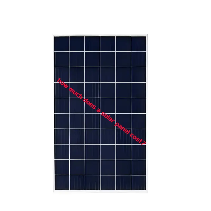
how much does a solar panel cost?how much does it cost to get solar panels? The cost of a solar panel can vary significantly based on several factors such as panel type, power – output, and installation requirements. Here is a detailed introduction: Panel – only cost: According to the price information on, the price of common small – power solar panels is generally between $0.05 and $0.75 per watt. For example, the price of a 150 – watt solar panel can range from about $7.5 to $112.5, with a large number of products concentrated in the range of $20 – $50. High – power industrial solar panels, such as the JA Solar JAM72D40MB 580 – 605 – watt panel, is about $46 per piece, equivalent to about $0.07 – $0.08 per watt. Cost of solar panel systems: The average cost of solar panels per watt is between $2 and $3, and the current average cost per watt is $2.84. A typical American household needs a 10 – kilowatt (kW) system to power their home, which costs about $28,241 in 2025, and the price drops to $19,873 after considering the federal solar tax credit. For an average 6.5 – kW system, the cost ranges from $16,600 to $20,500 before accounting for tax credits or rebates. Other influencing factors: The installation cost of solar panels is about $2.25 per watt, which includes labor, office work, and other mechanical expenses. In addition, the cost of solar inverters is between $350 and $3,200, and the cost of a whole – home solar battery is between $1,700 and $9,000. There is also a permit cost for installing solar panels, which is between $75 and $450 for residential use. In general, the cost of solar panels is affected by many factors. If you want...
Details
08/26/2025
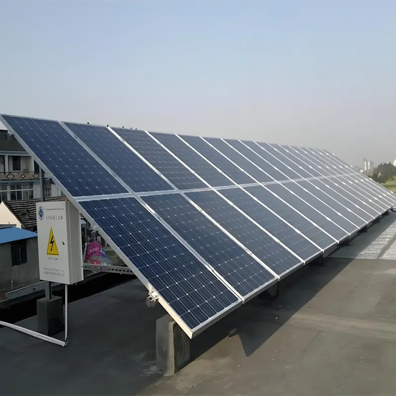
How Many Solar Panels Does It Take to Power a House? The number of solar panels needed to power a house varies widely—it depends on three core factors: your household’s total energy usage, the power output of the solar panels you choose, and the amount of sunlight your home receives (location-specific). Below is a step-by-step breakdown to calculate the exact number, plus real-world examples and key considerations. Step 1: Calculate Your Household’s Daily Energy Usage First, you need to know how much electricity your home consumes. This data comes from your utility bill (measured in kilowatt-hours, kWh). Find your monthly kWh usage: Look for the “total energy used” line on your bill (e.g., 900 kWh/month). Convert to daily usage: Divide monthly usage by 30 (the average number of days in a month). For example:900 kWh/month ÷ 30 days = 30 kWh/day. Note: For accuracy, use 12 months of bills to account for seasonal changes (e.g., higher AC use in summer or heating in winter). In the U.S., the average household uses ~893 kWh/month (per the U.S. Energy Information Administration, 2023), which equals ~29.8 kWh/day (rounded to 30 kWh/day). Step 2: Determine Solar Panel Power Output Solar panels are rated by their peak power output (measured in watts, W, or kilowatts, kW). Most residential panels today range from 350 W to 450 W (0.35 kW to 0.45 kW) per panel. For example: A standard 400 W panel produces 400 watts of electricity at peak sunlight (typically 10 AM–4 PM, when the sun is strongest). Step 3: Account for Sunlight Hours (Location Matters) Not all homes get the same amount of sunlight. The term “peak sun hours” (PSH) describes how many hours per day your area receives sunlight strong enough to power panels at their peak output. Sunny regions (e.g., Arizona, California, Nevada): 5–7...
Details
08/26/2025
Are Solar Panels Worth It? Whether solar panels are “worth it” depends on your location, financial situation, energy needs, and environmental priorities—there is no one-size-fits-all answer. Below is a detailed breakdown of the key factors to consider, along with a balanced assessment of their pros and cons. 1. Core Factor 1: Economic Viability (The Most Critical Consideration) The financial value of solar panels hinges on balancing upfront costs against long-term savings and potential incentives. Here’s a breakdown: A. Upfront Costs The initial investment includes equipment, installation, and permits. As of 2024, the average cost in the U.S. is $2.50–$3.50 per watt (before incentives), meaning a typical 5kW system (enough for a small-to-medium home) costs $12,500–$17,500. Cost components: Solar panels (40–50% of total cost): Monocrystalline panels (higher efficiency, ~22–26%) are more expensive than polycrystalline ones (~15–20%). Inverter (15–20%): Converts DC power from panels to AC for home use; microinverters (per-panel) cost more than string inverters but improve efficiency. Installation (20–30%): Labor, roof repairs (if needed), and permits. Optional add-ons: Battery storage (e.g., Tesla Powerwall, ~$10,000–$15,000 extra) for backup power or off-grid use. B. Long-Term Savings: How Much Will You Save? Savings come from reduced or eliminated electricity bills and potential revenue from selling excess power (via “net metering”). Electricity rate: If you pay high utility rates (e.g., >$0.20/kWh in places like California, Hawaii), savings will be faster. For example: A 5kW system in California generates ~7,000 kWh/year. At $0.30/kWh, this saves **$2,100/year** on bills. In a state with low rates (e.g., $0.10/kWh in Louisiana), savings drop to **$700/year**. Net Metering: Most utilities let you sell excess power back to the grid at retail rates, effectively “storing” energy as credits for nighttime or cloudy days. This can offset 80–100% of your bill. C. Incentives & Rebates (Reduce Upfront Costs) Government and local programs significantly lower costs. As of 2024:...
Details
08/26/2025
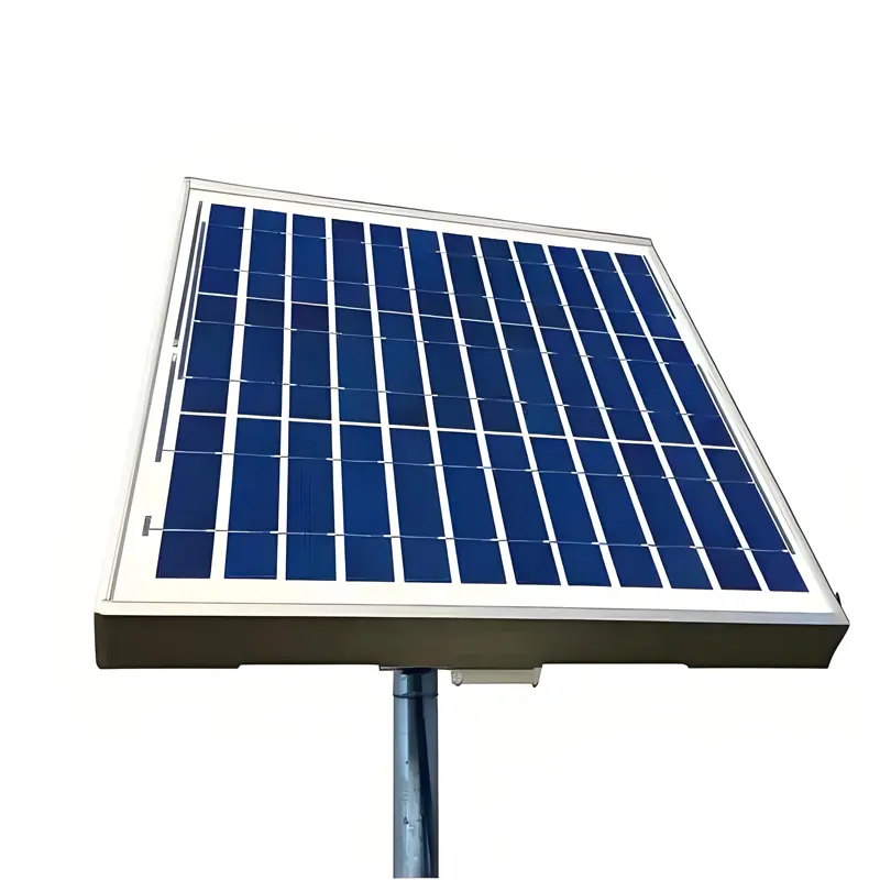
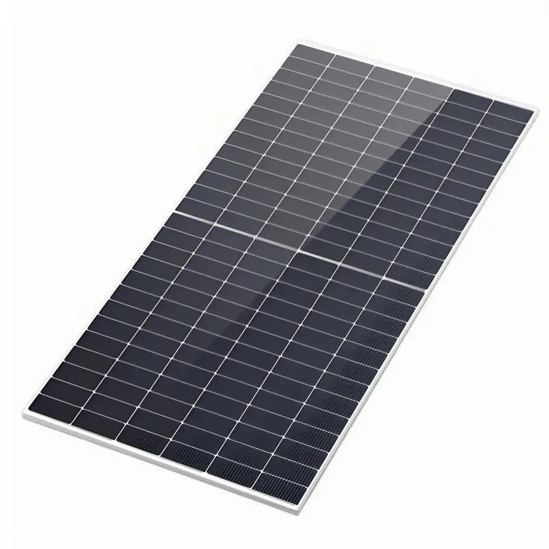
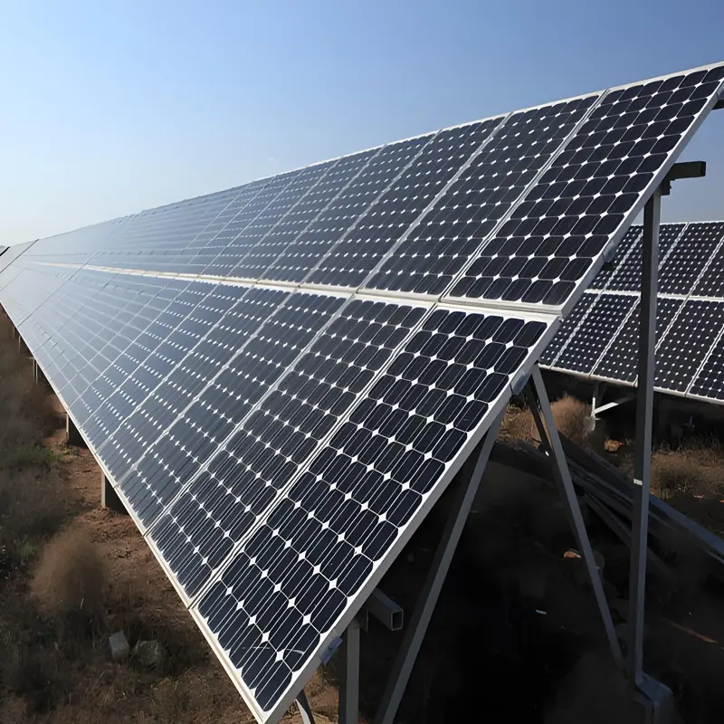
What Are Solar Panels?Working Principle A solar panel is a device that absorbs sunlight and directly or indirectly converts solar radiant energy into electrical energy through the photoelectric effect or photochemical effect. Material Composition A solar panel mainly consists of tempered glass, EVA (Ethylene Vinyl Acetate), solar cells, a backsheet, an aluminum alloy frame, a junction box, and silica gel. Among these components, silicon is the core material. Their respective functions are as follows: Tempered glass: Protects the solar cells while allowing sunlight to pass through. EVA: Bonds and fixes the tempered glass to the solar cells (or “bonds and secures the tempered glass and solar cells together”). Solar cells: The core component responsible for generating electricity. Backsheet: Provides sealing, insulation, and waterproofing. Aluminum alloy frame: Offers structural support and enhances the panel’s sealing performance. Junction box: Protects the entire power generation system and acts as a “current transfer station”. Silica gel: Seals the joints between the panel and the aluminum alloy frame, as well as between the panel and the junction box. Working Principle Taking crystalline silicon (the most common material) as an example: P-type crystalline silicon is doped with phosphorus to form N-type silicon, creating a P-N junction. When sunlight hits the surface of the solar cell, some photons are absorbed by the silicon material. The energy of these photons is transferred to silicon atoms, causing electrons to “jump” (i.e., become excited) and turn into free electrons. These free electrons accumulate on both sides of the P-N junction, forming a potential difference. When an external circuit is connected, the electrons flow through the external circuit under the influence of this potential difference, generating an electric current—thus converting light energy into electrical energy. Material Classification Crystalline silicon solar panels: Include polycrystalline silicon solar panels and monocrystalline silicon solar panels. Monocrystalline silicon panels have a...
Details
08/25/2025
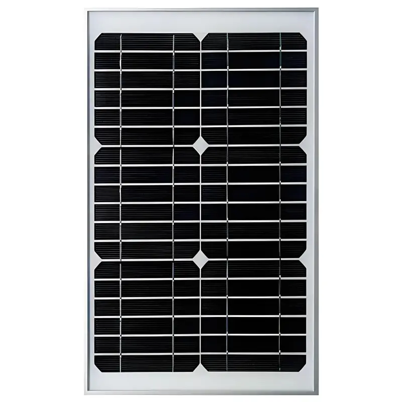
How Much Do Solar Panels Cost? In-Depth Analysis of Price Composition and Influencing Factors The price of solar panels varies significantly, influenced by multiple factors such as power output, type, brand, quality, as well as market supply and demand and raw material prices. Below is a detailed breakdown for you: I. Price Ranges by Power Output 1. Low-Power Solar Panels Low-power solar panels are commonly used in small devices or experimental scenarios, with typical specifications like 10W and 15W. For polycrystalline silicon models: A 10W polycrystalline solar panel costs approximately ¥65.65, while a 15W polycrystalline solar panel is around ¥4.2 per unit for bulk purchases. For monocrystalline silicon models: A 10W monocrystalline solar panel is roughly ¥4.3. These panels are affordable due to their low power output and minimal material usage, making them suitable for consumers with limited budgets and low electricity needs—such as powering small garden lights or charging toys. 2. Medium-Power Solar Panels The 100W–300W range is widely used in residential distributed photovoltaic (PV) systems. A 100W monocrystalline solar panel has a broad price range, from ¥70.59 to ¥707.85. For 150W solar panels, the price per watt on the international market generally falls between $0.05 and $0.75. Converted to RMB, a single 150W panel typically costs ¥30 to ¥50. Higher-power models like 450W monocrystalline solar panels have a price per watt of approximately ¥0.57 to ¥1.00. Medium-power panels are ideal for supplementing daily electricity needs in ordinary households, as they can power lighting and small home appliances. 3. High-Power Solar Panels Panels with 400W or higher output are mainly used in large industrial power stations and centralized PV plants. Large industrial-grade panels with 580–605W output cost about $46 per unit, with a minimum order quantity (MOQ) of 36 units. A complete 5kW solar panel system generally ranges...
Details
08/25/2025
How Do Solar Panels Work?A Complete Guide to Their Principles & Efficiency Factors The core principle behind solar panels (also known as photovoltaic panels) is the photoelectric effect, which directly converts the energy of photons in sunlight into usable electrical energy. This entire process requires no combustion or mechanical movement, making it a clean and sustainable energy conversion technology. To understand how it works, we need to break down the process into three core stages: “material foundation → energy conversion → circuit output”. Below is a detailed explanation: I. Core Foundation: Semiconductor Materials and PN Junctions (Why Silicon?) The key component of a solar panel is the photovoltaic cell unit (silicon-based cells are currently the mainstream). Silicon has become the core material due to its unique “semiconductor properties”—it neither conducts electricity freely like metals (which have a large number of free electrons) nor completely blocks charge movement like insulators. Its conductivity can be precisely adjusted through “doping” (adding trace amounts of other elements), laying the groundwork for subsequent energy conversion. The silicon wafers in photovoltaic cells are specifically engineered into a PN junction structure (the physical core of power generation), which involves two key steps: P-type semiconductor: A small amount of boron (with only 3 outer-shell electrons) is doped into high-purity silicon. Silicon atoms normally form stable covalent bonds using their 4 outer-shell electrons; when boron is added, each boron atom “lacks 1 electron”, creating a large number of “holes” (can be understood as “positively charged vacancies”) in the silicon crystal. It is important to note that holes are not actual “positively charged particles” but rather “charge vacancies” left behind when electrons depart. When surrounding electrons fill these holes, the holes appear to “move in the opposite direction of electron flow”, which is equivalent to the directional movement of positive charges on a macroscopic...
Details
08/25/2025
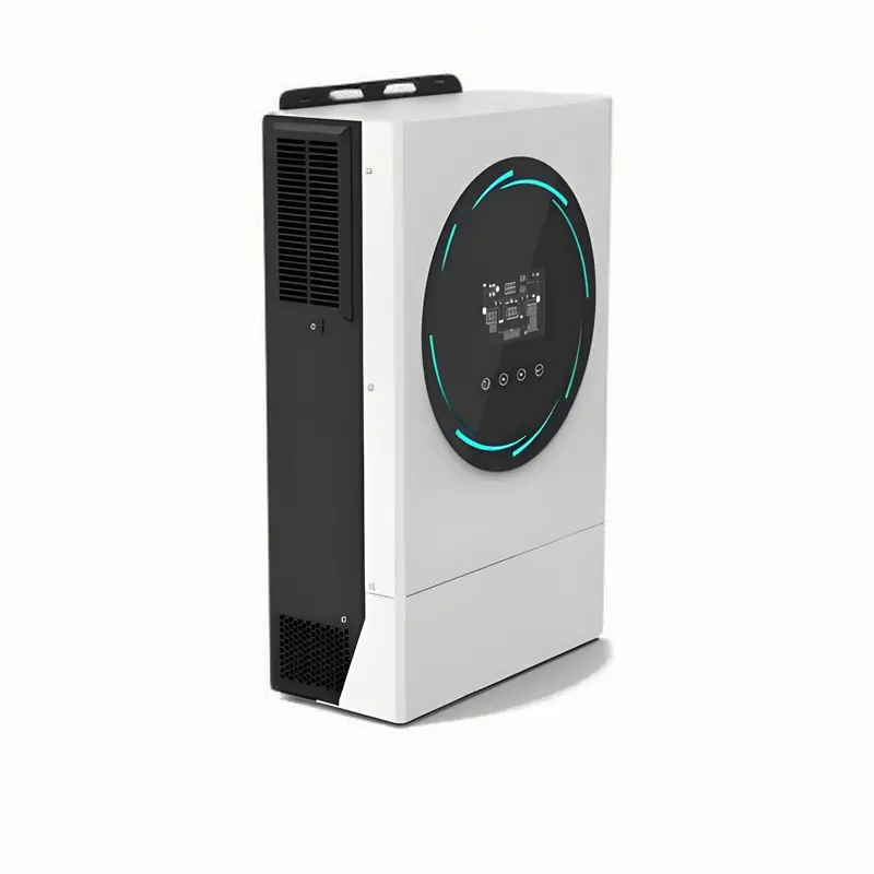
What Is the Typical Lifespan of a Solar Inverter? The lifespan of a solar inverter is not a fixed value; it is influenced by multiple factors such as product type, operating environment, maintenance quality, and technological iteration. The industry’s general reference range is 8–15 years. Some high-quality products can last more than 18 years under ideal conditions, while inferior products or those with improper maintenance may develop faults within 5 years. I. Core Influencing Factors: Key Variables Determining Lifespan Different factors affect the inverter’s lifespan to varying degrees, which can be categorized into the following 4 types: Influencing Factor Specific Performance Impact on Lifespan Product Type & Quality 1. Topology: Centralized inverters (high power, high heat dissipation pressure) vs. string inverters (distributed heat dissipation, stronger stability);2. Core components: Products using imported IGBTs (e.g., Infineon, Mitsubishi) and high-quality capacitors (high-temperature-resistant type) typically last 3–5 years longer than those using inferior components;3. Production standards: Products complying with IEC 62109 (solar inverter safety standard) and TÜV certification have stricter quality control. The most critical factor, directly determining the minimum lifespan. High-quality products can last over 50% longer than inferior ones. Operating Environment 1. Temperature: Long-term exposure to high temperatures above 40°C (e.g., rooftop sun exposure, enclosed spaces) accelerates capacitor aging, potentially shortening lifespan by 30%–50%;2. Humidity/corrosiveness: High salt spray in coastal areas and rainy, humid environments easily causes circuit board corrosion, while inverters in dry inland areas have relatively longer lifespans;3. Dust/sand: Without protective installation outdoors, dust accumulation clogs heat dissipation holes, leading to overheating faults. Lifespan is negatively correlated with environmental harshness. Extreme environments can shorten the lifespan of an inverter originally designed for 12 years to 6–8 years. Maintenance & Usage Habits 1. Regular cleaning: Cleaning dust from heat dissipation holes and fans quarterly prevents overheating;2. Voltage/load management: Avoid long-term overloading (e.g.,...
Details
08/25/2025
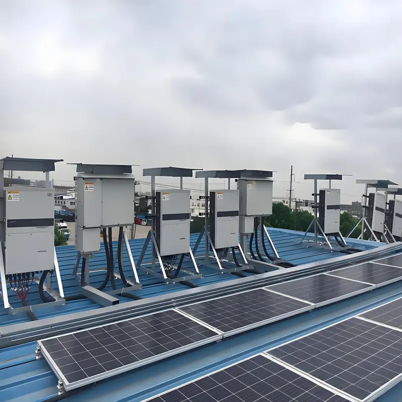
Pre-Installation Preparation for Solar Inverters: 8 Core Steps + Considerations (With Professional Advice) In a solar photovoltaic (PV) system, the inverter serves as the “energy conversion core,” and its installation quality directly affects the system’s power generation efficiency, safety, and service life. Comprehensive pre-installation preparation is crucial for avoiding subsequent malfunctions and reducing maintenance costs. Below is a detailed breakdown of the key pre-installation steps for solar inverters from the perspectives of on-site survey, equipment selection, qualification compliance, tools and materials, and safety protection—designed to help users advance their PV projects efficiently. I. Preliminary On-Site Survey: Accurately Matching the Installation Environment An on-site survey is the “fundamental prerequisite” for inverter installation. It is essential to confirm whether the environment meets the inverter’s operating requirements to prevent equipment overheating, malfunctions, or shortened service life due to unsuitable conditions. Confirm Installation Location and Space Prioritize areas with good ventilation and no obstructions (e.g., near rooftop PV brackets, ground-based equipment rooms, or outdoor rainproof cabinets). Ensure a minimum clearance of 50 cm around the inverter to facilitate heat dissipation and future maintenance. Avoid installing the inverter in locations exposed to direct sunlight (high temperatures in summer may trigger overheating protection), humid or waterlogged areas (humidity > 90% can damage circuits), or areas with high concentrations of dust or corrosive gases (e.g., near chemical plants). For outdoor installation, confirm that a rainproof, sunproof, and snowproof shelter can be built at the installation site (or select an outdoor inverter with an IP rating of IP65 or higher). Additionally, the ground must be level and have sufficient load-bearing capacity (a single inverter typically weighs 10–50 kg, so the installation surface should be rated to support ≥ 20 kg/㎡). Test Power Grid and Load Parameters Contact the local power grid company to obtain grid connection parameters, including grid voltage level (220V single-phase...
Details
08/25/2025
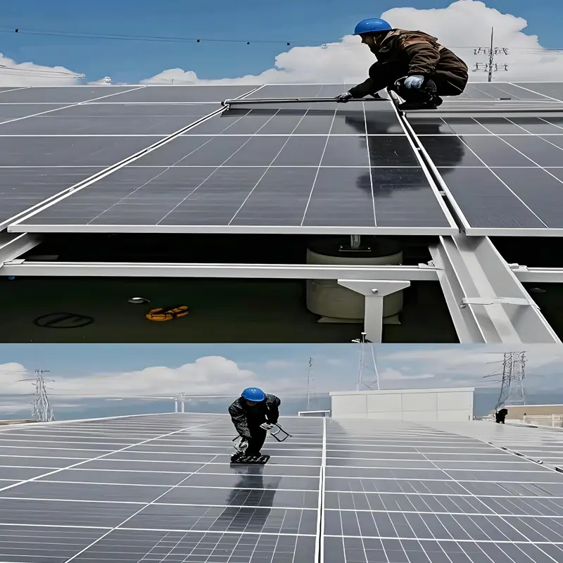
Must-Read for Beginners: A Complete Guide to Installing a Solar Inverter (From Preparation to Inspection, Pitfall Avoidance Tips) For beginners new to solar energy systems, installing a solar inverter is a core step that connects solar panels to electrical devices—it directly affects system efficiency and operational safety. Following the principles of “safety first, clear steps, and beginner-friendliness”, this article will guide you through the correct installation of a solar inverter step by step, from pre-installation preparation to post-installation inspection, and help you avoid common mistakes. I. Pre-Installation Essentials: 3 Core Prerequisites (That Determine Installation Success) Before starting the installation, be sure to confirm the following 3 points to avoid rework or safety risks caused by insufficient preparation: 1. Clarify Inverter Type and Applicable Scenarios Installation requirements vary significantly across different inverter types. Beginners should first select an inverter based on their solar system type: Inverter Type Applicable Scenarios Key Installation Features String Inverter Residential PV systems (5-50kW) Compact size, flexible installation (can be wall-mounted or floor-standing) Central Inverter Large-scale power plants (100kW+) Large size, requires an independent equipment room, and must be installed by professional teams Microinverter Distributed low-power systems (single solar panel) Installed directly under solar panels, with simple wiring Key Tip for Beginners: Prioritize string inverters for residential use, as they are easy to install and maintain. 2. Confirm Installation Environment (Meet These 2 Core Conditions) Inverters have strict environmental requirements; choosing the wrong location can reduce efficiency or even cause damage: Temperature Requirements: The typical operating temperature range is -25℃~60℃. Avoid direct sunlight (install a sunshade if necessary) and keep the inverter away from heat sources (e.g., air conditioner outdoor units, radiators). Protection Requirements: Indoor Installation: Choose a dry, well-ventilated room (such as a balcony or storage room) that is away from water sources and corrosive gases....
Details
08/21/2025
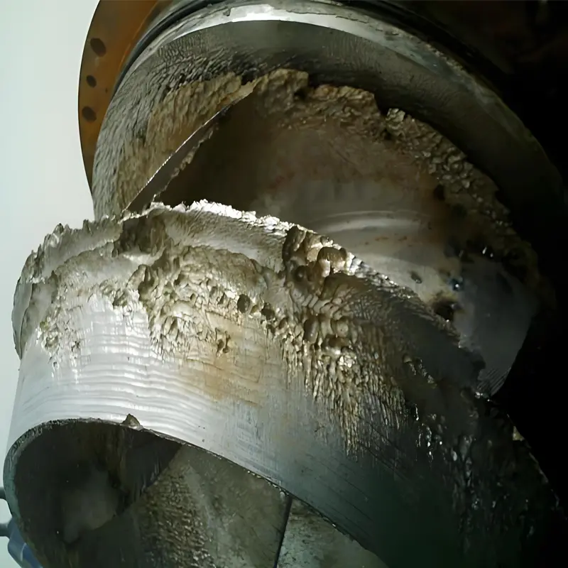
Cavitation in Pumps: A Comprehensive Guide to Hazards and Prevention Measures Cavitation in pumps is a common operational issue that severely impacts pump performance, lifespan, and stability. This article provides a detailed analysis of cavitation, covering its definition, key hazards, and effective preventive strategies. I. What Is Pump Cavitation? Pump cavitation occurs when liquid flowing through a pump experiences a local pressure drop to the liquid’s saturated vapor pressure at its current temperature. This causes the liquid to vaporize, forming numerous bubbles. As these bubbles move with the liquid into high-pressure zones, they collapse rapidly due to increased pressure. The surrounding liquid then rushes into the voids left by the collapsing bubbles at high speed, creating intense water hammer (with impact forces reaching hundreds or even thousands of MPa). This repeated impact on the pump’s wetted components (e.g., impellers, pump casings) triggers a series of adverse effects. II. Key Hazards of Cavitation Cavitation harms pumps in multiple ways, including: 1. Mechanical Damage (Most Direct Impact) Erosion of wetted components: High-frequency water hammer from bubble collapse repeatedly strikes metal surfaces of impellers, pump casings, and guide vanes. This leads to pitting, indentations, or even spalling (known as “cavitation erosion”). Over time, impellers may become unbalanced due to local damage, and in severe cases, they can fracture entirely. Fatigue failure of components: The constant high-frequency impact induces metal fatigue, weakening mechanical strength and shortening service life. For example, impellers may fail as fatigue cracks expand over time. 2. Diminished Pump Performance Reduced flow rate and head: Cavitation bubbles occupy space in the flow path, reducing the effective flow area and lowering liquid flow rates. Additionally, energy is wasted on bubble formation and collapse, decreasing the pump’s effective head. Significant efficiency drops: Energy that should drive liquid transport is diverted to bubble dynamics, leading...
Details
08/21/2025
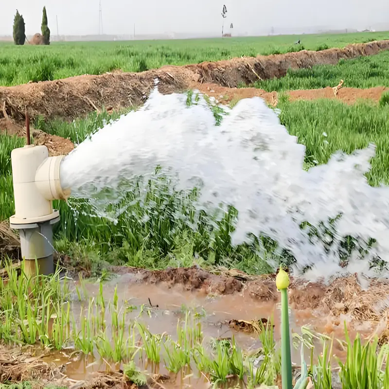
What Are the Methods for Preventing Failures in Agricultural Irrigation Pumps? Failures in agricultural irrigation pumps often stem from long-term neglect of preventive measures, allowing minor issues to accumulate into major breakdowns. According to actual operation and maintenance data, over 80% of pump failures can be avoided through scientific prevention. The following elaborates on targeted prevention methods from four dimensions: equipment selection and adaptation, standardized operation procedures, environmental protection, and regular inspection and early warning, helping users reduce downtime losses. I. Prevention Through Equipment Characteristics-Based Selection and Adaptation The root cause of pump failures may be laid during the selection stage. Improper matching can lead to long-term overload operation or performance waste, accelerating component aging. 1. Accurate Matching of Flow and Head Calculating Actual Requirements: Based on parameters such as irrigation area, crop water demand, and pipeline length, calculate the required actual flow (reference formula: Flow = Total water demand ÷ Daily operation time) and head (considering terrain elevation difference + pipeline resistance loss, where resistance loss accounts for approximately 10%-20% of the total head). For example, a 50-mu cornfield in the heading stage has a daily water demand of about 300 cubic meters. If it operates for 8 hours a day, the required flow is approximately 37.5 cubic meters per hour, and the head needs a 20% margin on top of the actual terrain elevation difference. Avoiding “Oversized Pumps for Small Tasks” or “Undersized Pumps for Large Tasks: The deviation between the selected flow and head and the calculated values should not exceed 10%. Oversized pumps operating under low load are prone to “surge,” causing fatigue damage to the impeller; undersized pumps operating under overload will cause the motor current to soar, triggering overheating protection or even burning the windings. 2. Material Adaptation to Water Quality Characteristics Water Sources...
Details