
08/21/2025
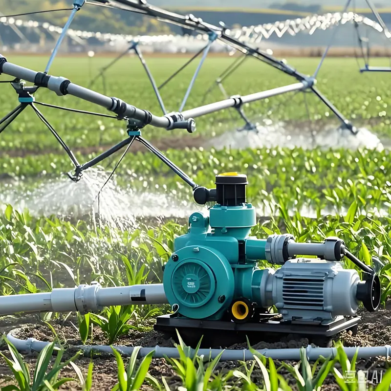
Maintenance and Servicing Methods for Agricultural Irrigation Pumps As the “heart” of field and greenhouse irrigation systems, the stable operation of agricultural irrigation pumps directly affects crop growth and yields. Due to long-term operation in outdoor, humid environments and water containing impurities, pumps are prone to issues like wear, corrosion, and blockages. Scientific maintenance and servicing can not only extend the equipment’s lifespan (typically by 30%-50%) but also ensure irrigation efficiency and reduce losses from unexpected shutdowns. The following outlines practical maintenance methods across four dimensions: daily inspections, regular servicing, seasonal maintenance, and fault prevention. I. Inspections and Maintenance During Daily Operation Quick inspections are required before and after each pump startup to identify potential issues promptly: 1. Basic Checks Before Startup Appearance and Connections: Check if the pump body and motor housing have cracks or deformations, if pipeline joints (flanges, threaded connections) are loose, and if sealing rings are aged. If water leakage is found, replace the sealing ring immediately or wrap it with Teflon tape for sealing. Lubrication and Cooling: Inspect the oil (grease) level in the bearing housing. Add the same type of lubricating oil when insufficient (No. 2 lithium-based grease for high-speed motors, No. 3 for low-speed motors), ensuring the oil level is between 1/2 and 2/3 of the oil sight glass. For water-cooled pumps, confirm the cooling water pipeline is unobstructed with no blockages or leaks. Impeller and Suction End: Clean weeds, sediment, and other debris from filters (such as foot valve filters and water inlet filters) to prevent impurities from entering the pump body during startup and causing impeller wear. For self-priming pumps, check if there is sufficient liquid in the pump casing (fill with priming liquid before the first startup). 2. Real-Time Monitoring During Operation Parameter Observation: Monitor outlet pressure and flow stability...
Details
08/21/2025
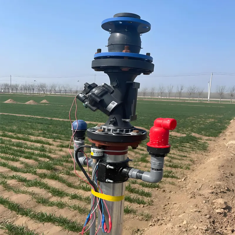
Agricultural Irrigation Pump Selection: Equipment Recommendations for Different Scenarios of Field and Greenhouse In agricultural production, irrigation is a key link to ensure the healthy growth of crops, and water pumps are the core equipment of the irrigation system. Different agricultural scenarios, such as fields and greenhouses, have significant differences in their requirements for water pumps. Reasonable selection can not only improve irrigation efficiency and reduce energy consumption but also extend the service life of equipment and save costs. This article will deeply discuss the key points of selecting agricultural irrigation pumps, provide professional equipment recommendations for field and greenhouse scenarios, and cover common needs such as “irrigation pump flow calculation” and “corrosion resistance requirements”. I. Calculation of Irrigation Pump Flow Accurately calculating the flow of the irrigation pump is the basis for selection. The determination of flow needs to consider multiple factors comprehensively: Farmland Area and Crop Water Requirement: Different crops have different water requirements at different growth stages. For example, in high-temperature summer, the daily water requirement of corn is about 2-3 liters per square meter, while that of vegetables may be higher. First, calculate the daily water requirement of crops per unit area, then multiply it by the total area of the farmland to get the total daily water requirement. Suppose a 1000-square-meter cornfield has a daily water requirement of 2.5 liters per square meter; the total daily water requirement is 1000 × 2.5 = 2500 liters. Irrigation Cycle: Considering the water supply and actual operational convenience, irrigation is not carried out every day. If the irrigation cycle is 3 days, the total water requirement of the above-mentioned cornfield every 3 days is 2500 × 3 = 7500 liters. Pump Working Time: Pumps cannot work continuously for 24 hours. Assuming it works 8 hours a day (the...
Details
08/21/2025
Causes and Solutions for Overheating of Water Pump Motors As the core power source of pump equipment, the normal operating temperature of a water pump motor is usually between 60-80°C (shell temperature). If it exceeds 90°C, it is considered significantly overheated, which not only accelerates component aging but may also trigger built-in protection mechanisms (such as thermal relay tripping) leading to shutdown or even motor burnout. This article focuses on motor faults themselves, analyzes common causes of overheating in water pump motors and targeted solutions, while addressing practical issues such as “overheating protection triggering”. I. Motor Overload: Load Exceeds Rated Capacity, Causing Current Surge and Overheating Motor overload is the most common cause of overheating. Essentially, when the output power exceeds the rated value, the current increases and winding heating intensifies. 1. Core Causes Pump Blockage: The impeller is stuck by debris (such as stones, fibers), or bearings are worn, or bushings are seized, causing a sudden increase in the motor’s rotational resistance and forcing it to output excessive torque. Mismatched Head: The actual operating head is much lower than the pump’s rated head, resulting in excessive flow (“high flow, low head” operation), and the motor load exceeds the rated value (for example, a pump with a rated head of 30 meters operating at 10 meters may have a flow rate increased by 1.5 times, with a corresponding surge in current). Abnormal Voltage: A low power supply voltage (e.g., 10% below the rated voltage) will cause the motor speed to drop, reduce electromagnetic conversion efficiency, and increase current (voltage is inversely proportional to current; lower voltage leads to higher current). Unbalanced three-phase voltage (with a difference exceeding 5%) can also cause excessive current in one phase of the windings. 2. Solutions Check for Blockages: After cutting off the power, manually...
Details
08/21/2025
Pump Energy-Saving Tips: How to Reduce Operating Energy Consumption? As core power equipment in industries, agriculture, construction, and other fields, water pumps account for a significant proportion of overall energy consumption. Statistics show that the energy consumption of pump systems accounts for approximately 10%-15% of global electricity consumption. Therefore, reducing operating energy consumption through scientific energy-saving transformations and technological applications can not only cut costs but also achieve green and low-carbon development. The following shares practical energy-saving tips focusing on core directions such as pump energy-saving transformation and application of frequency conversion technology. I. Pump Energy-Saving Transformation: Comprehensive Optimization from Equipment to System Excessive energy consumption of pumps often stems from equipment aging, unreasonable system design, or mismatched operating parameters. Significant energy savings can be achieved through targeted transformations. 1. Core Equipment Transformation: Improving Efficiency Benchmark Impeller Optimization and Replacement: The impeller of an old pump may have reduced hydraulic efficiency due to wear and corrosion. By redesigning the impeller (such as adopting a low-specific-speed, high-efficiency hydraulic model) or replacing it with a high-efficiency impeller, efficiency can be increased by 5%-15%. For example, replacing a traditional cast iron impeller with a stainless steel or engineering plastic impeller can not only reduce resistance but also extend the service life. Motor Upgrade: Eliminate inefficient motors and replace them with high-efficiency motors with high energy efficiency levels. High-efficiency motors can save 3%-8% of energy under rated working conditions by optimizing electromagnetic design and reducing iron loss and copper loss, which is especially suitable for long-term operating pump systems. Bearing and Seal Replacement: Worn bearings will increase mechanical loss, and poor-quality seals may cause water leakage and increase the pump’s load. Replacing them with high-precision rolling bearings and mechanical seals can reduce mechanical loss by 10%-20% and reduce maintenance frequency. 2. Pipeline System Transformation:...
Details
08/20/2025
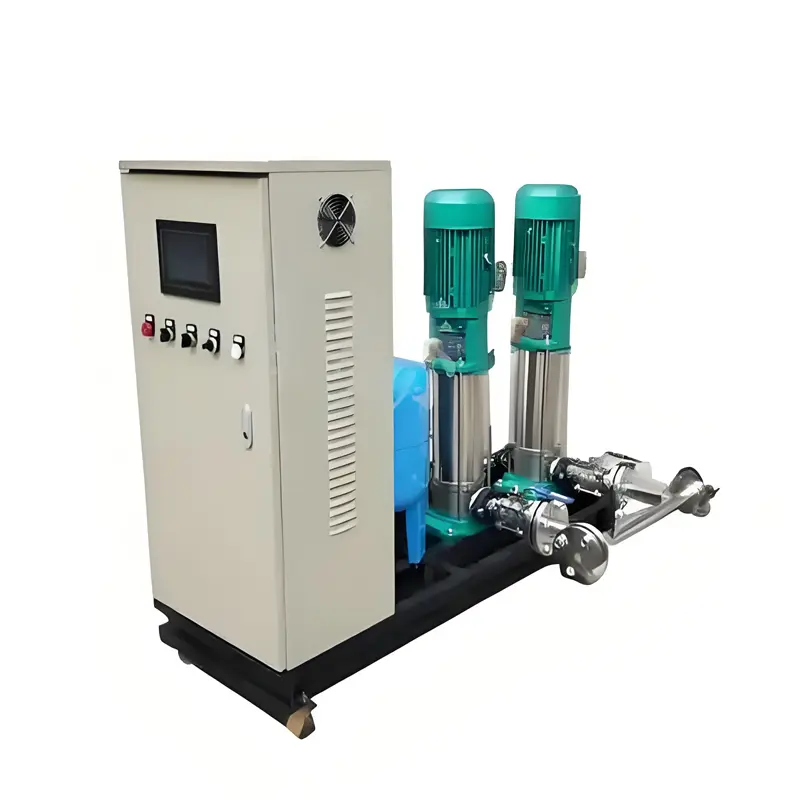
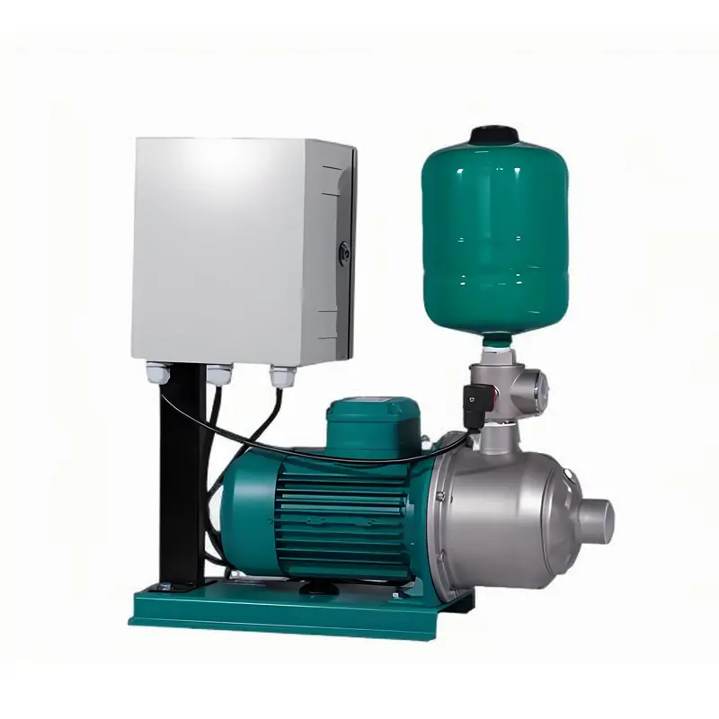
What is a Variable Frequency Pump? A variable frequency pump, also known as a VFD pump (Variable Frequency Drive pump), is a type of water pump equipped with a variable frequency drive to adjust its operating speed. Unlike traditional fixed-speed pumps that run at a constant speed, it can dynamically modify the motor’s rotational speed based on actual water demand, achieving energy-efficient and precise flow control. How Does a Variable Frequency Pump Work? The core of a variable frequency pump lies in the variable frequency drive (VFD), which converts the fixed-frequency alternating current (typically 50Hz or 60Hz) into adjustable-frequency power. This process allows the pump motor to change speed: When water demand increases, the VFD raises the frequency, increasing the motor speed and output flow. When demand decreases, the frequency is reduced, slowing the motor and conserving energy. Sensors (e.g., pressure sensors, flow meters) in the system monitor real-time conditions and send signals to the VFD, enabling automatic speed adjustments without manual intervention. Key Benefits of Variable Frequency Pumps Energy Efficiency: By matching speed to demand, they reduce energy consumption by 30%-50% compared to fixed-speed pumps (thanks to the affinity law, where power consumption is proportional to the cube of speed). Extended Lifespan: Lower operating speeds and reduced start-stop cycles minimize wear on components like motors and impellers. Stable Pressure/Flow: Maintains consistent water pressure in systems (e.g., residential plumbing, irrigation), avoiding fluctuations. Quiet Operation: Slower speeds reduce noise, making them suitable for noise-sensitive environments. Smart Control: Integrates with building management systems (BMS) for remote monitoring and automation. Common Applications Variable frequency pumps are widely used in various fields: Residential and Commercial Buildings: Water supply, heating, and air conditioning systems. Industrial Sector: Process water circulation, wastewater treatment, and manufacturing lines. Agriculture: Irrigation systems to optimize water usage based on...
Details
08/19/2025
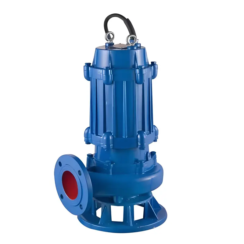
Say goodbye to blockages! How to choose a submersible sewage pump correctly? Selecting a suitable submersible sewage pump requires a comprehensive evaluation of actual usage scenarios, sewage characteristics, and equipment performance parameters. Below are key considerations and practical methods: 1. Clarify Sewage Properties: Match Anti-Clogging and Corrosion Resistance The core function of a submersible sewage pump is to handle impurity-laden fluids, so analyzing sewage composition is the first step: Solid particles and fiber content: For sewage with large amounts of sediment or small stones (e.g., construction site sludge), opt for pumps with large-channel impeller designs (channel width ≥ 1.5 times the particle diameter) to prevent blockages. For sewage containing easily tangled substances like long hair or cloth strips, prioritize models with cutting-type impellers (e.g., single or double-blade cutting designs), which can shred impurities before discharge. Corrosiveness and temperature: Ordinary domestic sewage: Cast iron pump bodies are suitable (cost-effective and resistant to mild corrosion). Industrial wastewater (containing acids, alkalis, or salts): Choose stainless steel (304/316) or engineering plastic (PVC/PP) materials to avoid component corrosion. High-temperature sewage (e.g., food processing wastewater over 60°C): Check the pump’s temperature resistance rating (typically -10°C to 100°C; custom high-temperature motors are needed for temperatures beyond this range). 2. Determine Core Parameters: Flow Rate (Q) and Head (H) These parameters directly define the pump’s “conveying capacity” and must be calculated based on actual needs: Flow rate (Q): The volume of sewage transported per unit time (units: m³/h or L/s). Estimation method: Base it on the “sewage generation volume.” For example, for household basement drainage, if the maximum daily displacement is 5m³ and the working time is 8 hours, the flow rate should be ≥ 0.6m³/h. For municipal sewage wells, calculate using the number of residents served (each person generates ~0.2m³ of sewage daily). Note: Reserve a 10%–20% margin to avoid insufficient flow during peak periods....
Details
08/19/2025
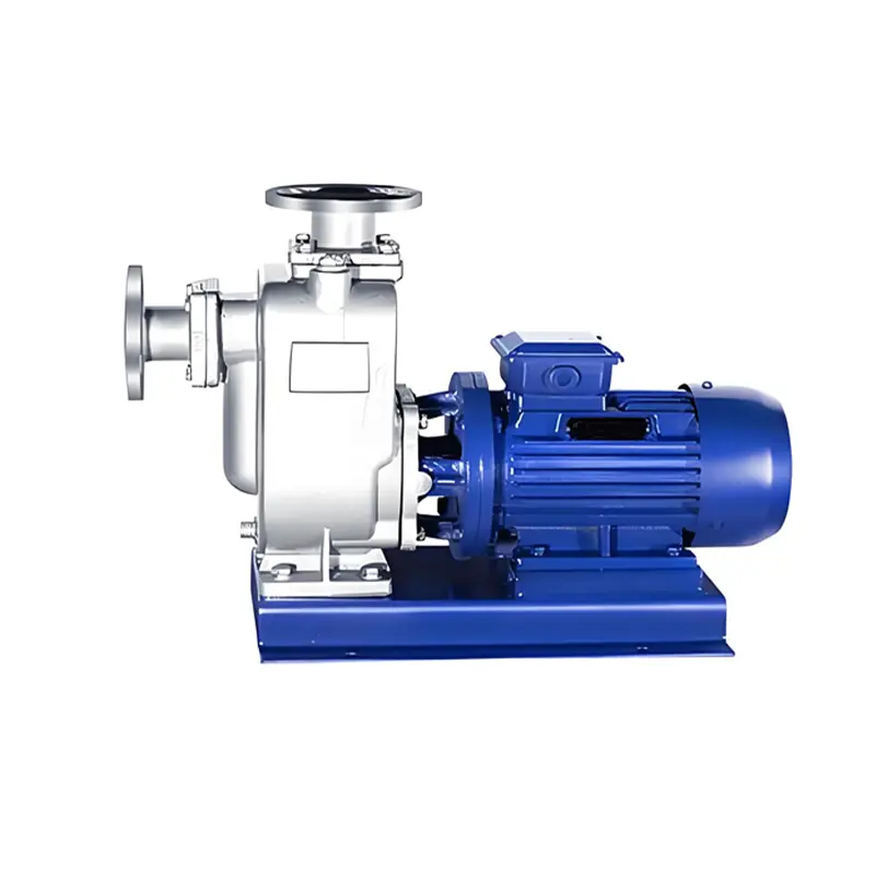
What is a Self-Priming Sewage Pump? A self-priming sewage pump is a specialized pump designed to transport sewage or wastewater containing solid particles, fibers, sludge, and other impurities, with inherent self-priming capabilities. Unlike traditional pumps, it does not require manual liquid filling into the pump casing before startup; instead, it can automatically draw in liquid through its unique structural design. It is widely used in municipal sewage discharge, industrial wastewater treatment, agricultural irrigation, construction site drainage, and other scenarios. I. Core Feature: Self-Priming Ability The key distinction between a self-priming sewage pump and a standard sewage pump lies in its self-priming capability. Ordinary centrifugal pumps must be primed (i.e., the pump casing and suction pipe filled with liquid) before startup to function; otherwise, they cannot pump water effectively. In contrast, self-priming sewage pumps—equipped with special structures like a built-in gas-liquid separation chamber—can automatically expel air from the pump and draw in liquid after inhaling a small amount of air during the first startup. For subsequent startups, re-priming is unnecessary, significantly enhancing operational convenience. II. Working Principle First Startup: A small amount of liquid is pre-stored in the pump (some models require manual addition of initial liquid, while others retain liquid automatically via their structure). When started, the impeller rotates, flinging out the liquid inside the pump while creating a vacuum in the suction pipe. Liquid Suction and Air Exhaust: External liquid is pushed into the suction pipe by atmospheric pressure. The gas-liquid mixture entering the pump is propelled toward the pump casing by centrifugal force. Air is expelled through the gas-liquid separation chamber, while the liquid flows back to the impeller, where it is flung out again. This process continues until all air is exhausted, enabling continuous pumping. Restart: A portion of liquid remains in the pump, allowing direct restart...
Details
08/19/2025
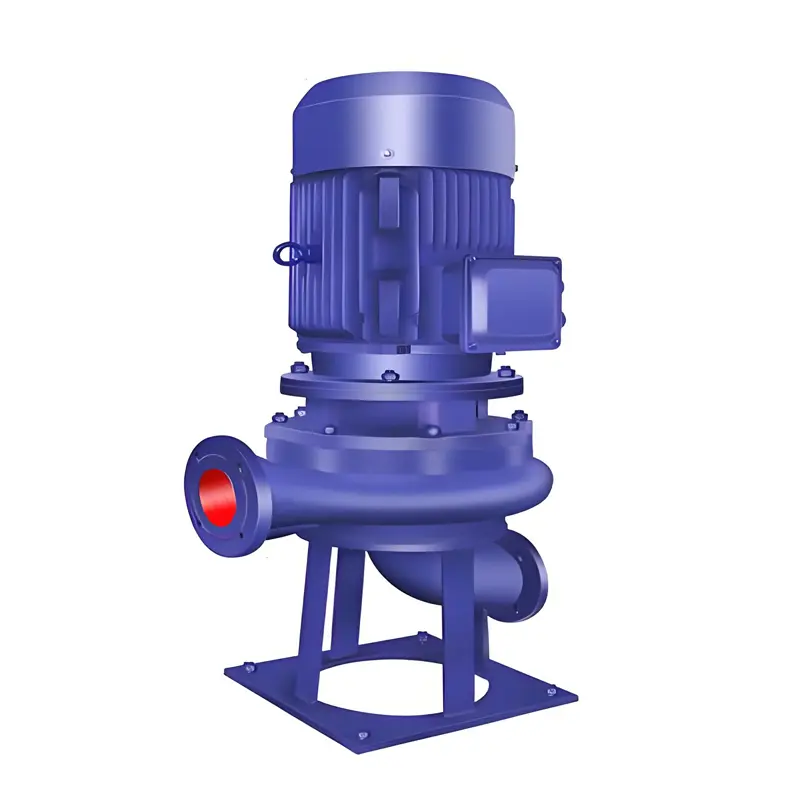
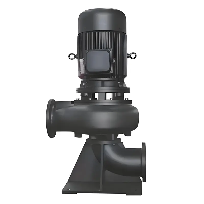
What Is a Dry-Type Sewage Pump? A dry-type sewage pump is a specialized pump designed to transport sewage containing solid particles, fibers, sludge, and other impurities. Its core rotating components (such as the motor and bearings) do not come into direct contact with sewage. Its design features a separation structure that isolates the motor from the sewage medium, preventing the motor from corrosion or damage caused by sewage—making it suitable for various harsh sewage environments. I. Core Structure and Working Principle The core structure of a dry-type sewage pump lies in “dry-wet separation,” mainly consisting of the following parts: Pump body: In direct contact with sewage, it contains an internal impeller. As the impeller rotates, it generates centrifugal force to suck in and discharge sewage. Motor: Serving as the power source, it connects to the pump body via a transmission structure (e.g., a coupling). The motor is completely isolated from sewage to prevent moisture damage, corrosion, or entanglement by impurities. Sealing device: At the connection between the pump body and the motor, mechanical seals or packing seals are typically used to prevent sewage from leaking into the motor compartment. II. Main Characteristics Strong corrosion resistance: The pump body is often made of cast iron, stainless steel, or engineering plastics, enabling it to resist sewage containing corrosive components such as acids and alkalis. Wide applicability: It can transport sewage with solid particles (e.g., sediment, gravel) and fibers (e.g., cloth strips, hair), making it ideal for municipal sewage treatment, industrial wastewater discharge, basement drainage, and more. Easy maintenance: Since the motor does not contact sewage, failure rates are low. Additionally, maintenance requires no direct contact with sewage, simplifying operations. Flexible installation: It can be installed in a fixed configuration (e.g., in a pump pit) or a mobile setup (e.g., portable sewage...
Details
08/19/2025
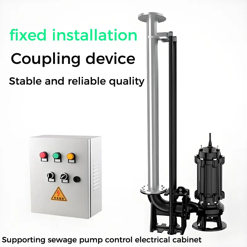
Submersible Sewage Pumps Submersible sewage pumps are devices designed to operate underwater for transporting sewage. They boast features like a compact structure and strong sewage-discharging capacity. Here’s a detailed overview: Structure and Working Principle Structure: The motor and pump are integrated into a single unit. The motor is powered via a cable, while the impeller and pump body are typically made from wear-resistant and corrosion-resistant materials. Working Principle: The motor drives the pump impeller to rotate, creating centrifugal force that draws in and discharges sewage. Key Characteristics Advantages: They have a compact structure and small footprint, allowing direct installation in sewage tanks without the need for a dedicated pump room. Installation and maintenance are convenient: small models can be installed freely, while large ones come with automatic coupling devices. They support long continuous operation. Since the pump and motor are coaxial, the shaft is short, rotating components are lightweight, and the bearing load is low. They eliminate issues like cavitation damage and the need for priming. Disadvantages: As they operate underwater and transport media containing solid materials, and given that the pump is close to the motor with a vertical arrangement, they have higher requirements than ordinary sewage pumps in terms of sealing, motor load capacity, bearing arrangement, and component selection. Scope of Application Industrial Applications: Suitable for factories, mines, and other sites, they can discharge industrial wastewater, mine sewage, etc. They are widely used in industries such as chemical engineering, petroleum, pharmaceuticals, mining, papermaking, cement plants, steel mills, and power plants to transport granular sewage and pollutants. Municipal Engineering: They can be used in drainage systems of urban sewage treatment plants, municipal drainage projects, construction site drainage, and more. Civil Buildings: Ideal for sewage drainage stations in residential areas, hospitals, hotels, and sewage discharge from high-rise buildings, among others....
Details
08/19/2025
What Is a Sewage Pump? A sewage pump is a type of pumping equipment specifically designed to transport sewage or wastewater containing solid particles, fibers, sludge, and other impurities. It is widely used in municipal engineering, industrial production, agricultural irrigation, construction sites, and domestic sewage disposal. Its core function is to handle the transportation of impurity-laden fluids. Compared with ordinary clean water pumps, it boasts stronger anti-clogging capabilities and durability. Core Features of Sewage Pumps Anti-clogging DesignSewage often contains impurities like sediment, paper scraps, hair, and fibers. Therefore, the flow passages (e.g., impellers and pump casings) of sewage pumps are usually designed to be wide and smooth to minimize impurity retention. Some impellers feature a cutting structure, which can chop fibers and small particles to prevent clogging. Corrosion ResistanceIndustrial sewage or chemical wastewater may contain corrosive substances such as acids and alkalis. The wetted components of sewage pumps (e.g., pump bodies and impellers) are made of corrosion-resistant materials like stainless steel and engineering plastics (PVC, PP) to extend their service life. Adaptability to Harsh Working ConditionsSewage pumps typically operate in humid, muddy environments or even those with flammable and explosive gases. As a result, their motor parts are designed with a sealed structure (e.g., IP68 protection rating) to prevent water or dust intrusion. Some models also have explosion-proof functions to meet the needs of special scenarios. Classification of Sewage Pumps (by Structure and Installation Method) Submersible Sewage Pumps: The motor and pump body are integrated, allowing them to submerge directly into sewage for operation without the need for additional suction pipes. They are suitable for low-liquid-level scenarios (e.g., sewage pools, catch basins) due to their easy installation and space-saving design. Dry-type Sewage Pumps (Horizontal/Vertical): The motor is separated from the pump body, which is installed on the ground or above...
Details
08/18/2025
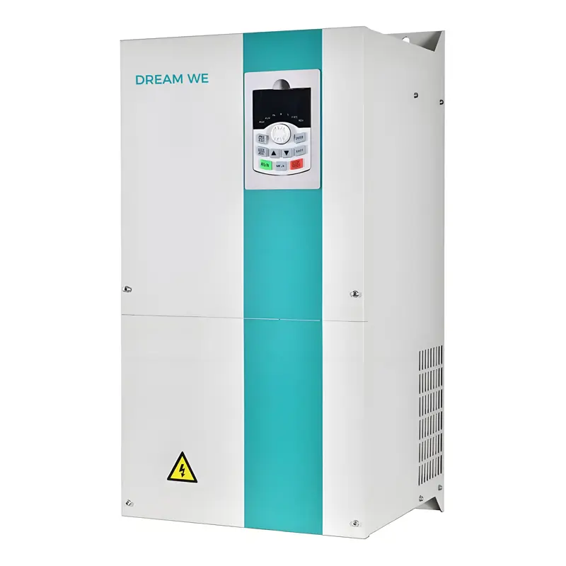
How to Correctly Select a Water Pump Frequency Converter Proper selection of a water pump frequency converter (VFD) is crucial to ensuring efficient compatibility and stable operation with the water pump system. It requires comprehensive consideration of factors such as pump motor parameters, load characteristics, control requirements, and environmental conditions. Below are specific selection steps and key points: 1. Clarify Core Parameters of the Pump and Motor The primary function of a frequency converter is to regulate motor speed, so it is essential to first accurately match the motor’s key parameters: Power Matching The rated power of the frequency converter must equal or slightly exceed the power of the water pump motor (a 10%-20% margin is recommended). For example: a 5.5kW pump motor should be paired with a frequency converter of ≥5.5kW to prevent frequent shutdowns or burnout caused by an underpowered converter. If the pump experiences frequent starts or sudden load fluctuations (e.g., when a sewage pump handles debris), the margin can be increased to 30%. Voltage and Phase Confirm whether the pump motor is single-phase (220V) or three-phase (380V), and select a frequency converter with the corresponding voltage type. Note: Some three-phase converters support single-phase input (check the manual for details), but single-phase motors cannot be connected to three-phase converters. Speed Range Determine the speed range supported by the frequency converter based on the pump’s required flow adjustment range. For instance: centrifugal pumps typically require 0-3000rpm (for 50Hz power supplies), while deep well pumps may need lower speeds (e.g., 0-1500rpm). Ensure the converter’s speed range covers actual operational needs. 2. Analyze the Pump’s Load Characteristics Different types of pumps have distinct load characteristics, which directly influence the functional requirements of the frequency converter: Centrifugal/clean water pumps: These are “square torque loads,” where flow is proportional to speed, and...
Details
08/18/2025
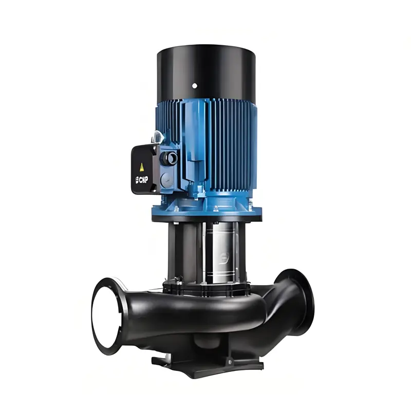
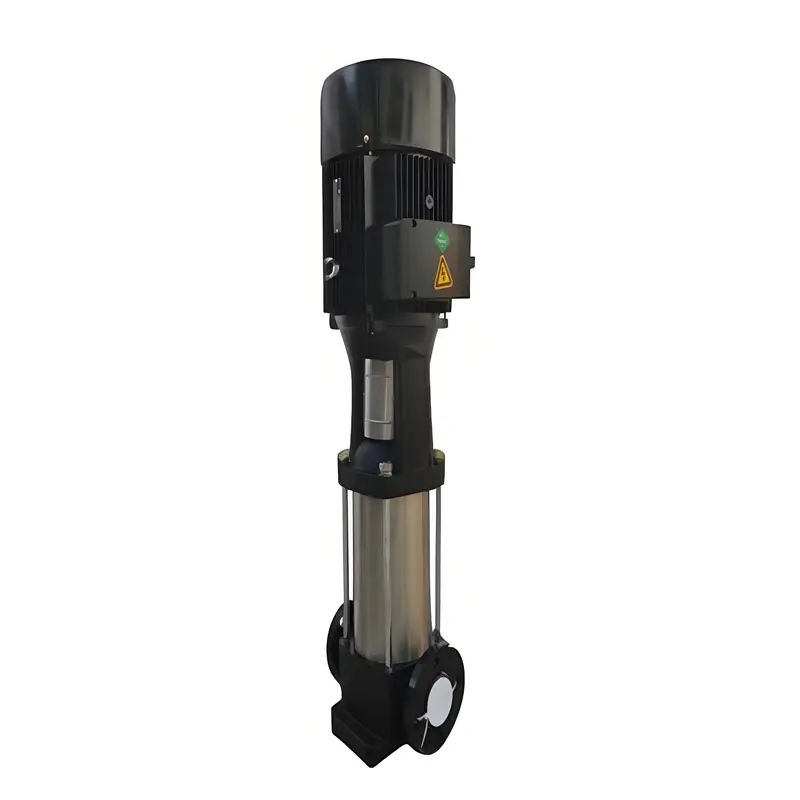
What Is a Centrifugal Pump? A centrifugal pump is a fluid-handling device that moves liquids using centrifugal force. It is widely used in agricultural irrigation, industrial circulation systems, urban water supply, sewage treatment, and many other fields, making it one of the most common pump types. Core Components of a Centrifugal Pump A centrifugal pump consists of several key parts that work together to transport liquids effectively: Impeller: The rotating core component, typically fitted with curved blades and mounted on the pump shaft. It generates the centrifugal force needed to move liquids. Pump casing (volute): A spiral-shaped shell enclosing the impeller (resembling a snail’s shell). It collects the liquid thrown by the impeller and converts the liquid’s kinetic energy into pressure energy (i.e., increasing the liquid’s pressure). Pump shaft: Connects the motor to the impeller, transmitting rotational power from the motor to drive the impeller. Suction chamber: Located just before the impeller inlet, it guides liquid smoothly into the impeller, minimizing flow resistance and energy loss. Sealing mechanism: Such as mechanical seals or packing glands, which prevent liquid from leaking along the pump shaft. Motor: Serves as the power source, driving the rotation of the pump shaft and impeller. How a Centrifugal Pump Works The operation of a centrifugal pump relies on the generation and application of centrifugal force, following these steps: Priming before startup: Before the pump operates, the pump casing and suction pipe must be fully filled with liquid (a process called “priming”). If air is trapped inside, the low density of air means the rotating impeller cannot generate enough centrifugal force to create the necessary low pressure, preventing liquid from being drawn in (a problem known as “air binding”). Generating centrifugal force: The motor spins the impeller at high speeds (typically 1450 rpm or 2900 rpm)....
Details