
08/18/2025
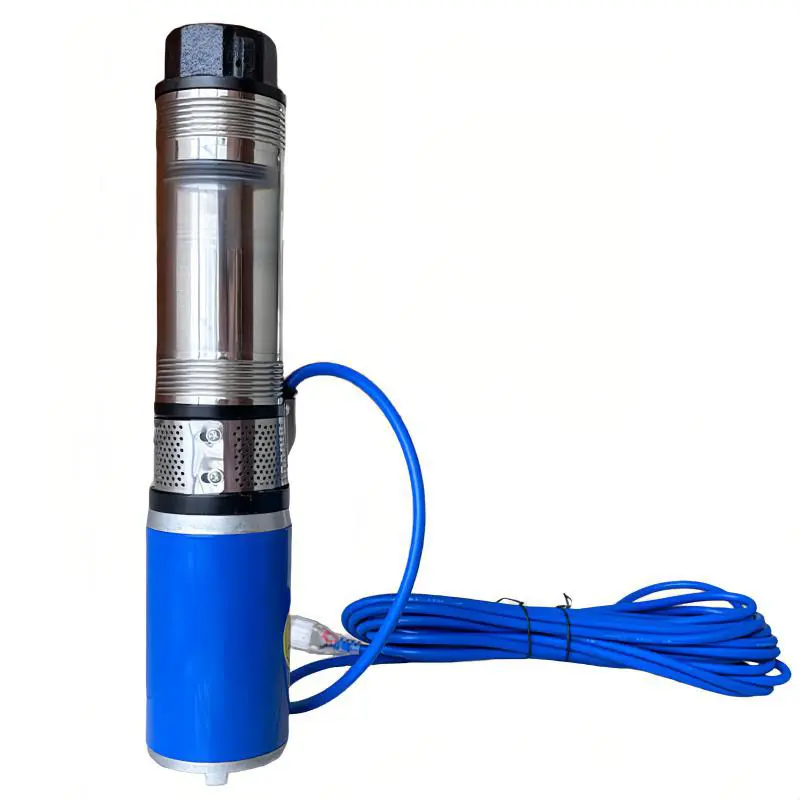
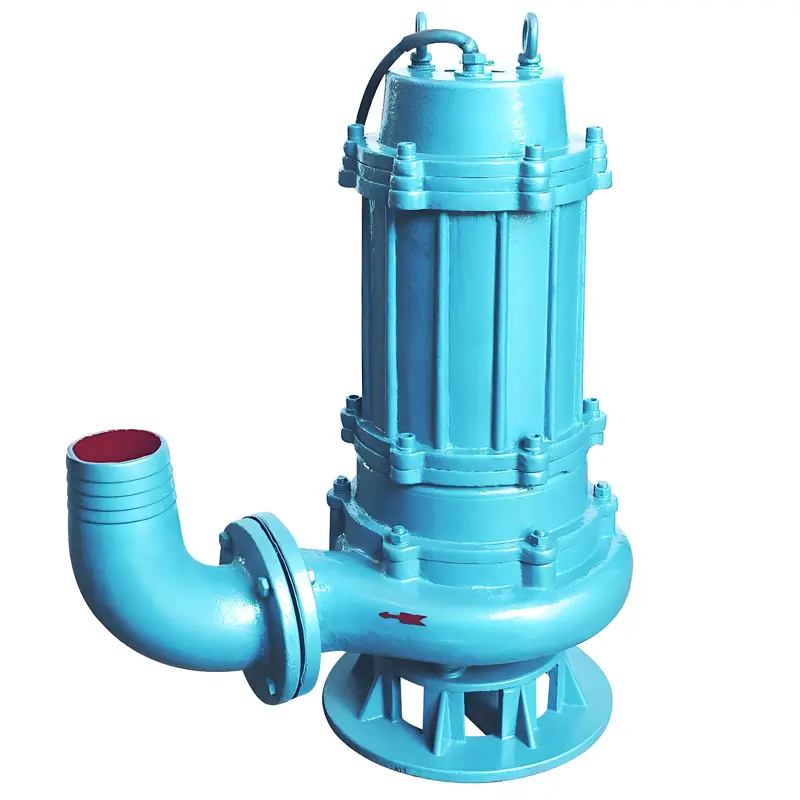
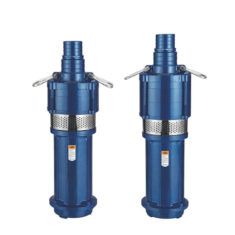
What Is a Submersible Pump? A submersible pump is a water-pumping device that operates with its pump body directly immersed in water. It is primarily used to extract liquids from deep wells, pools, rivers, lakes, and other water sources, and is widely applied in agricultural irrigation, industrial drainage, urban water supply, household drainage, and emergency rescue scenarios. Structural Features of Submersible Pumps Integrated design: The motor and pump are typically assembled into a single unit, eliminating the need for additional transmission components (such as couplings or drive shafts). Its compact structure allows for easy immersion in water. Waterproof sealing: The motor is equipped with robust waterproof sealing measures (e.g., mechanical seals, O-rings) to prevent water from entering the motor, which could cause short circuits or damage. Submersible operation: During operation, the entire pump body (including the motor) is fully submerged in liquid. This design uses the liquid to cool the motor while reducing suction-related inefficiencies, thereby improving pumping performance. Working Principle of Submersible Pumps When a submersible pump starts, the motor drives the impeller to rotate at high speed. Under centrifugal force, liquid within the impeller is propelled toward the impeller’s edge, creating a low-pressure zone at the impeller’s inlet. External atmospheric pressure then pushes liquid from the water source through the suction pipe into the impeller. The liquid is continuously expelled and transported to the desired location via the outlet pipe. Types of Submersible Pumps Based on application scenarios and structural differences, submersible pumps fall into several categories: Deep-well submersible pumps: Ideal for extracting water from deep wells. Their slender design enables them to adapt to deep water levels. Sewage submersible pumps: Specifically engineered to handle sewage, sludge, and other impurity-laden liquids. Their impellers and pump bodies feature anti-clogging designs. Clean-water submersible pumps: Used for pumping clean water...
Details
08/15/2025
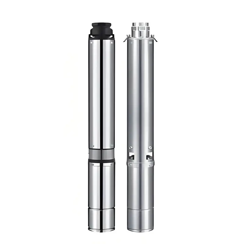
What Is a Deep Well Pump? A Complete Guide to Its Types & Uses A deep well pump is a mechanical device specifically designed to extract liquids (primarily water) from deep wells, groundwater layers, or other deep water sources. Its design is characterized by the ability to adapt to relatively great depths for water extraction, making it widely used in scenarios such as agricultural irrigation, industrial water supply, urban water supply, and groundwater monitoring. Core Structure and Working Principle of Deep Well Pumps The structure of a deep well pump typically includes the pump body, motor, riser pipe, transmission shaft, and other components. Its working principle relies on centrifugal force or positive displacement transfer: Motor drive: The motor is usually installed on the ground and connected to the downhole pump body via a transmission shaft, providing power for pumping water. Liquid conveying: The pump body is positioned below the downhole water surface. When the motor starts, the impeller inside the pump body rotates at high speed, generating centrifugal force to draw water into the pump before transporting it to the ground via the riser pipe. Main Types of Deep Well Pumps Based on differences in working principles and structures, deep well pumps can be categorized into the following types: Centrifugal deep well pumps: The most common type, which pumps water through the centrifugal action of the impeller. They are suitable for medium to low-depth wells (usually tens of meters deep). Submersible electric pumps: The motor and pump body are integrated, allowing them to work entirely submerged in water without a long transmission shaft. They are ideal for deeper wells (up to hundreds of meters deep) and are easier to install and maintain. Screw-type deep well pumps: These transport liquids through the meshing movement of screws and bushings, making them...
Details
08/15/2025
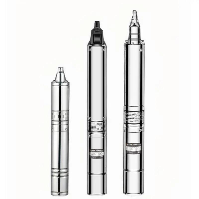
How to Install Deep Well Water Pumps in Rural Areas: A Beginner’s Guide In rural areas where municipal water isn’t available, deep wells (often 50–300 feet deep) are lifelines for households, farms, and small communities. A properly installed deep well pump ensures reliable access to clean water for drinking, irrigation, and livestock. This guide walks through the entire process—from selecting the right pump to final testing—with tips tailored to rural conditions. Understanding Rural Deep Well Scenarios Rural deep wells come with unique challenges that influence pump selection and installation: Variable well depth: Wells may range from 50 feet (shallow deep wells) to over 300 feet, depending on the water table depth. Remote locations: Limited access to electricity (may rely on generators or solar) and professional services. Harsh conditions: Extreme temperatures, dust, and occasional flooding require durable equipment. Multi-purpose use: Water may need to serve homes, barns, and irrigation systems—demanding consistent pressure. For these scenarios, submersible deep well pumps are preferred over jet pumps. They’re submerged in water, more energy-efficient for deep depths, and less prone to priming issues—critical for remote areas. Step 1: Choose the Right Deep Well Pump Selecting the correct pump ensures efficiency and longevity. Key factors: 1. Well Depth & Water Level Measure the static water level (depth from ground to water when the well is unused) and total depth (ground to well bottom). Example: A well with a total depth of 200 feet and a static water level at 80 feet requires a pump rated for at least 120 feet of “lift” (distance from the water to the ground). 2. Flow Rate (GPM) Calculate based on usage: A 4-person household needs 10–15 GPM. Add 5–10 GPM for irrigation or livestock watering. 3. Power Source Electric: Most common if grid power is available (230V is standard for rural pumps). Solar: Ideal...
Details
08/14/2025
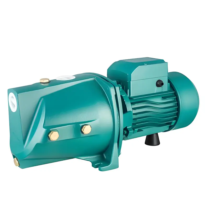
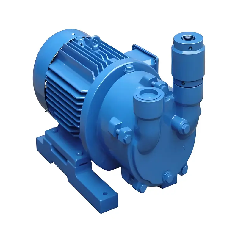
What Is a Jet Pump? A Complete Guide for Selection & Use Jet pumps are versatile water pumps widely used in residential, agricultural, and light industrial settings—especially for shallow to moderately deep wells, boosting water pressure, and transferring fluids. Unlike submersible pumps that operate underwater, jet pumps are installed above ground. They use a unique “jetting” mechanism to draw water from sources like wells, tanks, or lakes. Below is a detailed guide to help you understand how they work, their applications, and how to choose the right one. How Does a Jet Pump Work? A jet pump operates on Bernoulli’s principle—using high-velocity water flow to create low pressure (suction) that pulls water from a source. Here’s a step-by-step breakdown of its operation: Motor & Impeller: An electric motor drives an impeller, which pushes water through a narrow nozzle (the “jet”). Jet Action: The nozzle speeds up the water flow, creating a vacuum in the suction line connected to the water source. Water Intake: This vacuum draws water from the source into the pump, where it mixes with the high-velocity water from the nozzle. Pressure Boost: The combined water then flows into a diffuser, which slows the flow and converts its velocity into pressure, pushing the water through pipes to its destination. Key note: Most jet pumps need priming (filling the pump and suction line with water) to start—they can’t pull air, so that initial water charge is essential. Types of Jet Pumps Jet pumps are categorized by their design and intended use. The two most common types for residential and light commercial use are: 1. Shallow Well Jet Pumps Best for: Wells with water tables less than 25 feet (7.6m) deep. Design: Has a single impeller and a jet assembly mounted directly on the pump. Pros: Easy to install, lower cost,...
Details
08/13/2025
Water Pump Selection Guide: Centrifugal pump vs submersible pump: which one is more suitable for household water supply systems? When setting up a home water supply system (whether drawing from a well, tank, or municipal line), choosing between a centrifugal pump and a submersible pump depends on your specific needs—like water source depth, installation space, noise tolerance, and maintenance preferences. Below is a detailed comparison to help you decide. What Are Centrifugal and Submersible Pumps? 1. Centrifugal Pumps Working principle: Installed above ground, they use a rotating impeller to create centrifugal force, drawing water into the pump and pushing it through pipes. Key feature: Requires priming (filling the pump and suction pipe with water) to work—they can’t “suck” water from too deep without help. Typical use: Shallow water sources (wells ≤7m deep), tanks, or boosting pressure in municipal lines. 2. Submersible Pumps Working principle: Fully submerged in water (e.g., at the bottom of a well or tank), they push water upward using a hermetically sealed motor and impeller. Key feature: No priming needed—water surrounds the pump, so it starts instantly. Typical use: Deep wells (>7m), underground tanks, or where space above ground is limited. Core Comparison: Centrifugal vs. Submersible for Home Use To simplify your decision, here’s a side-by-side breakdown of key factors for home water supply: Factor Centrifugal Pump Submersible Pump Water Source Depth Best for shallow sources (≤7m). Limited by “suction lift” (max ~7m, due to atmospheric pressure). Ideal for deep sources (>7m). Can handle wells/tanks 10m–100m deep. Installation Installed above ground (needs a dry, sheltered spot near the water source). Requires a suction pipe from the source to the pump. Installed underwater (lower part of the well/tank). No need for a separate suction pipe—connected directly to the discharge pipe. Noise Level Noisier (motor and impeller run above ground; vibrations may...
Details
08/13/2025
Water Pump Selection Guide: How to choose a suitable water pump based on flow rate and head? When selecting a water pump, flow rate and head are the two core parameters that directly determine whether the pump can meet your actual needs. Choosing incorrect parameters may result in insufficient water supply, excessive energy consumption, or even equipment damage. Below is a detailed guide to selecting a pump based on flow rate and head, including key steps and considerations: I. Understanding Core Parameters: Flow Rate (Q) and Head (H) 1. Flow Rate (Q): Volume of Fluid Delivered Per Unit Time Units: Cubic meters per hour (m³/h), liters per second (L/s), or gallons per minute (GPM). Note conversions: 1 m³/h ≈ 0.278 L/s ≈ 4.403 GPM. How to calculate: Base it on your “total water demand” or “required delivery speed.” Example 1: A household with 3 bathrooms (each faucet uses ~0.6 m³/h) needs a total flow rate of at least 1.8 m³/h to meet simultaneous use. Example 2: For agricultural irrigation, if 1,000㎡ of land requires 5 m³ of water per mu (667㎡) per hour, the pump needs a flow rate of at least 5 m³/h. 2. Head (H): The Vertical Height a Pump Can Deliver Water (Including Resistance Loss) Units: Meters (m) or feet (ft), where 1 m ≈ 3.28 ft. What makes up total head? Actual (geometric) head: The vertical distance between the water source and the outlet. For example, pumping from a 10m-deep well to a 3m-high tank gives an actual head of 13m. Pipe resistance loss: Energy lost as water flows through pipes, valves, or elbows. This depends on pipe material, diameter, and length (typically 10%-30% of the actual head). Safety margin: Add 10%-20% to the total head to account for fluctuations (e.g., water level changes or pipe aging). Formula: Total Head = Actual Head...
Details
08/12/2025
How to choose a water pump and what precautions should be taken? Selecting a water pump is critical to ensuring its efficient, stable operation. The process requires comprehensive analysis of actual needs, medium properties, and environmental conditions. Below are detailed steps and considerations for pump selection: I. Core Steps for Water Pump Selection 1. Define Key Requirement Parameters This forms the foundation of selection. Accurately calculate or confirm the following: Flow rate (Q): The volume of fluid to be transported per unit time (e.g., m³/h, L/s). Determine based on specific scenarios: for instance, domestic water supply depends on peak water usage, while industrial lines rely on total equipment water consumption. Head (H): The total resistance the pump must overcome, consisting of three parts: Geometric head: Vertical height difference between the fluid’s source and destination (e.g., from a tank to a rooftop reservoir). Pipeline resistance: Friction in straight pipes (related to pipe diameter, length, and fluid velocity). Local resistance: Resistance from valves, elbows, tees, and other fittings.Note: Reserve a 10%-20% head margin during selection to account for potential resistance increases due to pipeline aging or changes in fluid viscosity. 2. Analyze Fluid Characteristics The physical and chemical properties of the fluid directly determine the pump type. Focus on: Fluid type: Clean water (e.g., tap water), sewage (with suspended solids), corrosive liquids (e.g., acids/alkalis), particle-laden fluids (e.g., sludge), or high-temperature fluids (e.g., boiler water). Key properties: Viscosity: High-viscosity fluids (e.g., oil, syrup) require positive displacement pumps (screw pumps, gear pumps) rather than centrifugal pumps, which are inefficient for thick fluids. Corrosiveness: Acidic or alkaline fluids need corrosion-resistant pumps (made of stainless steel, fluoroplastic, etc.). Solid content: Fluids with particles (e.g., sediment, waste) require sewage pumps (with cutting impellers or wear-resistant materials). Temperature: High-temperature fluids (e.g., >80℃) demand heat-resistant pumps (with...
Details
08/11/2025
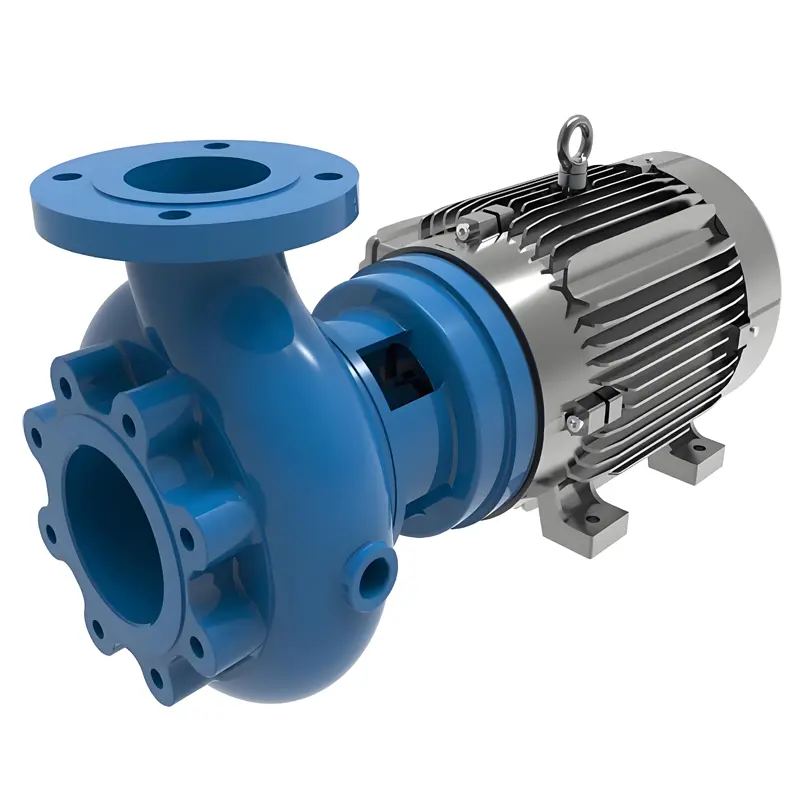
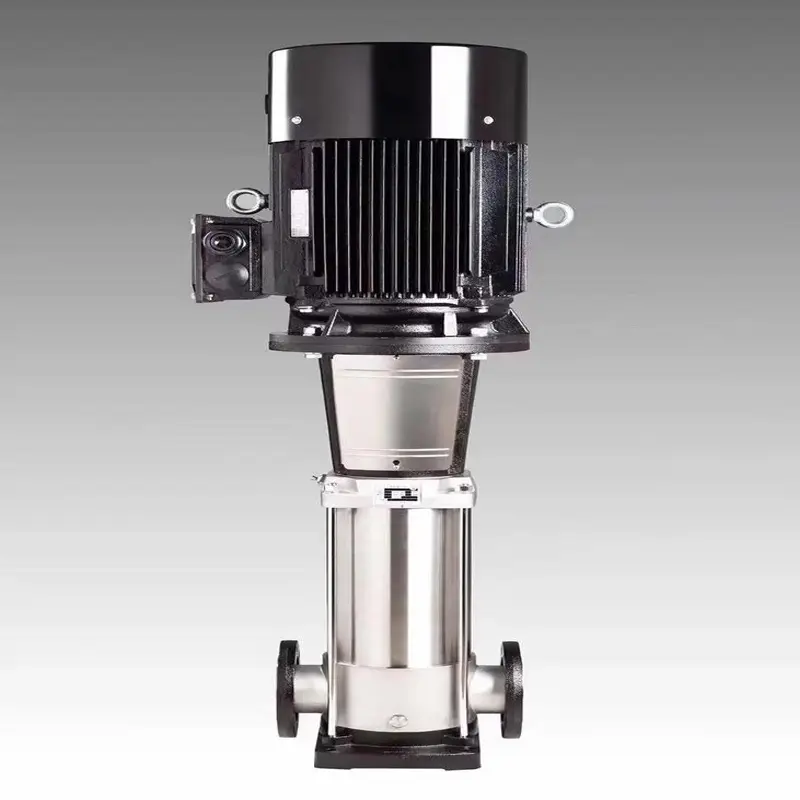
Centrifugal pumps are widely used fluid-handling devices in both industrial and residential settings, with classifications based on working principles, structural features, and application scenarios. Below are the four primary types: 1. Single-Stage Single-Suction Centrifugal Pump Structural Features: A single impeller is mounted on the pump shaft, and liquid is drawn into the impeller from only one side (single-suction design). Advantages: Simple structure, compact size, lightweight, low manufacturing costs, and easy maintenance. Applications: Ideal for low to moderate flow and head requirements, such as urban water supply/drainage, agricultural irrigation, and small-scale industrial cooling systems. Examples: Household clean water pumps, small industrial chillers. 2. Single-Stage Double-Suction Centrifugal Pump Structural Features: The impeller has suction inlets on both sides, allowing liquid to enter from two directions simultaneously. This design delivers approximately twice the flow rate of a single-suction pump of the same size, with a larger impeller diameter enabling higher head. Advantages: High flow capacity, efficient operation (dual-suction design reduces axial thrust), and stable performance. Applications: Suited for high-flow scenarios, including large water treatment plants, power plant circulating water systems, and agricultural irrigation stations. Examples: SH-type double-suction centrifugal pumps, split-case centrifugal pumps. 3. Multistage Centrifugal Pump Structural Features: Multiple impellers are connected in series on a single shaft. Liquid passes through each impeller sequentially, with total head increasing through “step-by-step pressurization” (total head ≈ head per impeller × number of impellers). Advantages: Exceptionally high head (capable of reaching hundreds or even thousands of meters), making it suitable for high-pressure fluid transfer. Applications: Used in high-head, medium-to-low flow situations, such as high-rise building water supply, mine dewatering, and boiler feedwater systems. Examples: D-type multistage centrifugal pumps, industrial boiler feed pumps. 4. Self-Priming Centrifugal Pump Structural Features: Equipped with a liquid storage chamber and a recirculation channel. No manual priming is needed before startup (though...
Details
08/11/2025
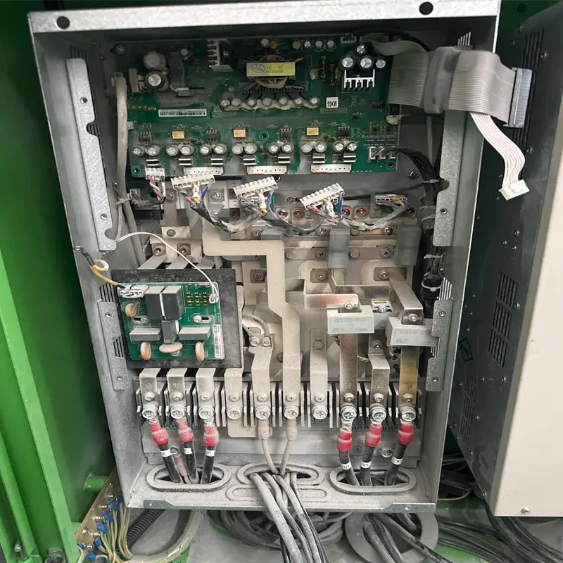
How to Clean and Maintain a Frequency Converter As a key piece of equipment in industrial automation, the cleaning and maintenance of frequency converters directly impact their operational stability and service life. Below are detailed cleaning and maintenance methods, along with important precautions: 1. Preparation for Cleaning and Maintenance 1.1 Safety Precautions Disconnect the frequency converter’s main power and control power supplies, ensuring the power indicator light is off. Wait for capacitors to discharge (typically 10–15 minutes; high-power models may require longer). Confirm discharge is complete by measuring the DC bus voltage, which should drop below 36V. Wear insulated gloves and anti-static wristbands, and use insulated tools (e.g., insulated screwdrivers) to avoid static electricity or electric shock risks. 1.2 Tool Preparation Cleaning tools: Soft-bristled brush (lint-free), high-pressure air gun (with dry, oil-free compressed air), industrial vacuum cleaner, anhydrous alcohol (or specialized electronic cleaner), and dust-free cloths. Inspection tools: Multimeter (for voltage testing) and torque wrench (to tighten screws to specified levels, preventing over-tightening or loosening). 2. Cleaning Steps 2.1 External Cleaning Wipe the inverter’s casing, control panel, and heat dissipation grilles with a dust-free cloth dampened with a small amount of anhydrous alcohol to remove surface oil and dust. For stubborn dust in grille gaps, use a soft-bristled brush to loosen it, then vacuum away residues. 2.2 Internal Cleaning (Requires Casing Removal, for Cabinet or Detachable Models) Cooling Fan and Filter: Remove the fan cover and use a high-pressure air gun to blow dust from the fan blades and filter (direct air from inside to outside to avoid pushing dust into internal circuits). Filters can be removed, rinsed with clean water, and reinstalled only after fully drying. Check for fan noise or jamming; replace immediately if faulty. Circuit Boards and Components: Use a high-pressure air gun (set to low pressure...
Details
08/11/2025
How to Select a Submersible Sewage Pump Selecting a submersible sewage pump requires comprehensive consideration of actual working conditions (such as medium characteristics, drainage requirements, and installation environment). Improper selection can lead to low efficiency, frequent failures, or even equipment damage. Below are detailed selection steps and key points, covering critical parameters and scenario-specific adaptation principles: 1. Clarify Medium Characteristics: Determine Pump Structure and Material Based on Sewage Composition The core function of a submersible sewage pump is to transport sewage. The physical and chemical properties of the medium directly influence the pump’s material, impeller design, and protective features. Focus on the following: Solid particle content and sizeIf sewage contains solids like sand, gravel, silt, or construction debris (e.g., construction site drainage, river dredging), choose an impeller with cutting/tearing capabilities (such as vortex impellers or single/double-blade cutting impellers) to prevent clogging. For particles larger than 50mm, ensure the flow passage diameter is at least 1.5 times the maximum particle size.Example: When pumping sewage with 20–30mm gravel, select a cutting-type pump with a flow passage diameter of ≥40mm. Fibers and viscous substancesFor wastewater with high levels of long fibers (e.g., hair, cloth strips, pulp in domestic sewage or dyeing wastewater), use anti-clogging impellers (e.g., open impellers, spiral impellers). Optimize the gap between the impeller and pump casing (typically ≤3mm) to reduce blockages from fiber entanglement. Corrosiveness and temperatureFor sewage containing acids/alkalis (e.g., chemical or electroplating wastewater) or high temperatures (over 60°C), upgrade materials accordingly: Mild corrosion (pH 6–8): Cast iron pump body + stainless steel impeller. Moderate corrosion (pH 4–10): All stainless steel (304 grade). Severe corrosion (pH <4 or >10): Special alloys (e.g., 316L) or rubber/lined plastic. High-temperature sewage (60–100°C): Use a high-temperature motor (insulation class ≥F) and replace standard rubber seals with fluororubber. Density and viscosityIf sewage density exceeds 1.2g/cm³...
Details
08/11/2025
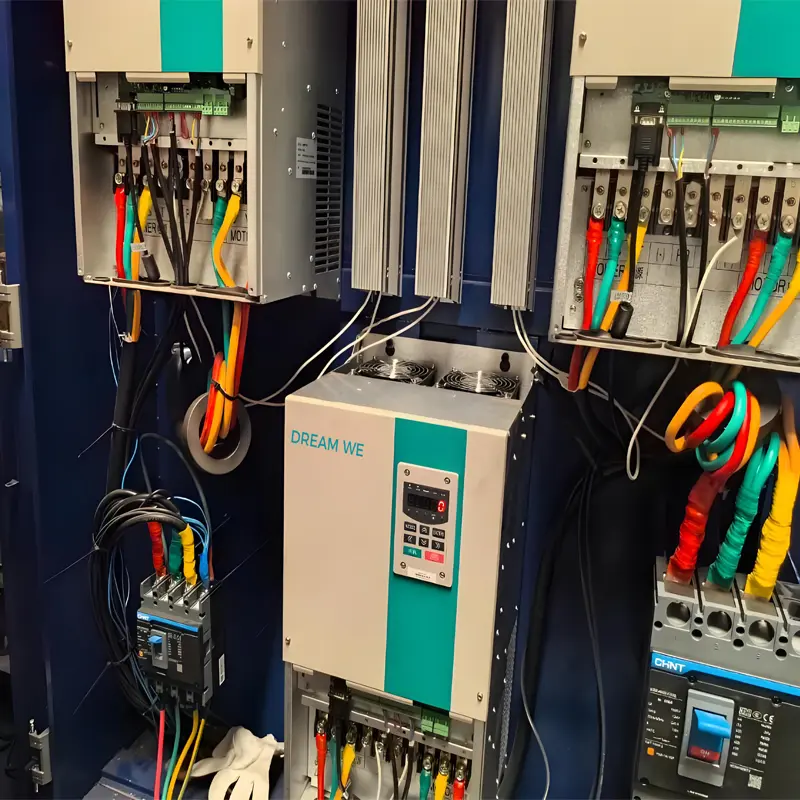
Common Causes of Frequency Converter Damage A Variable Frequency Drive (VFD) is a critical piece of equipment in industrial automation and motor control. Its damage can lead to production disruptions and increased maintenance costs. Below are the common causes of frequency converter failure, covering electrical, environmental, operational, and maintenance factors, with specific scenario examples: 1. Electrical Factors: Overcurrent, Overvoltage, and Power Supply Irregularities Abnormal input voltageExcessively high grid voltage (e.g., voltage surges from lightning strikes or transformer malfunctions) or abnormally low voltage (e.g., due to excessive grid load) can damage internal components like rectifier bridges and electrolytic capacitors.Example: During a thunderstorm, without a surge protector installed, high-voltage pulses can travel through power lines into the frequency converter, burning out the rectifier module. Output-side short circuits or ground faultsMotor winding short circuits, damaged cable insulation causing ground faults, or loose motor terminals creating arcing can trigger sudden spikes in the converter’s output current. This may overwhelm overcurrent protection mechanisms and even burn out IGBT power modules.Example: In a humid environment, aging motor cables develop cracks, leading to a ground short. When the converter’s overload protection fails, the power unit is destroyed. Frequent start-stops or sudden load changesHigh-frequency start-stop cycles (e.g., frequent jogging operations) can cause excessive current surges inside the converter. Sudden load increases (e.g., a jammed conveyor belt) may lead to motor stalling and subsequent overcurrent.Example: Crane equipment that lifts and lowers frequently subjects the converter to long-term overload. Insufficient heat dissipation causes power modules to overheat and fail. 2. Environmental Factors: Temperature, Humidity, and Contamination Poor heat dissipationHigh ambient temperatures (exceeding the converter’s rated operating range, typically 40–50°C), faulty cooling fans, or dust-clogged heat sinks can cause internal components—especially power modules and capacitors—to overheat, leading to aging or burnout.Example: In a textile workshop, lint accumulates over the converter’s cooling...
Details
08/08/2025
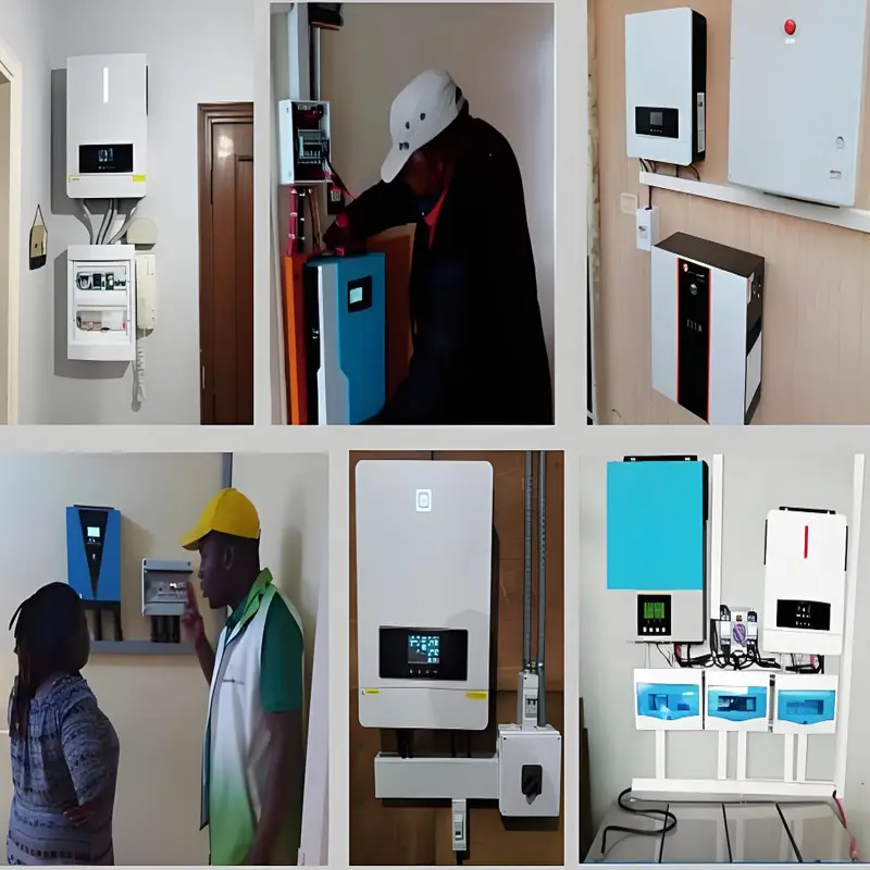
Types of Solar Inverters Solar inverters are core components of solar photovoltaic (PV) systems, responsible for converting direct current (DC) generated by solar panels into alternating current (AC) to meet electricity needs in residential, industrial, and other scenarios. Based on different classification criteria, solar inverters can be divided into various types. Here is a detailed introduction to common classifications: 1. Classification by Phase According to the phase of output AC, solar inverters are divided into single-phase inverters and three-phase inverters, mainly used to match different power grids or load requirements: Single-phase inverters: Output single-phase AC (e.g., 220V), suitable for small-scale PV systems such as residential homes and small commercial buildings. They power single-phase appliances like TVs and refrigerators. Three-phase inverters: Output three-phase AC (e.g., 380V), ideal for medium to large PV systems such as industrial plants and large-scale solar farms. They match three-phase loads like three-phase motors and large central air conditioners, offering higher efficiency and stability. 2. Classification by Capacity/Power Based on rated power, inverters are categorized into micro, small, medium, and large types, corresponding to PV systems of different scales: Micro-inverters: Typically with a power range of 200W-1000W, they connect directly to one or a few solar panels (e.g., 1-2 modules). They optimize the power generation efficiency of each panel individually, reducing the impact of shading, dust, etc., on the overall system. Suitable for distributed low-power scenarios (e.g., scattered installation on residential rooftops). Small inverters: With power ranging from 1kW to 10kW, they are commonly used in residential or small commercial PV systems. They require a combiner box to balance the current from multiple panels. Medium inverters: Power ranges from 10kW to 50kW, suitable for medium-sized commercial buildings, agricultural PV, etc. They can connect multiple strings of panels, balancing efficiency and cost. Large inverters: Power exceeds 50kW, even reaching several megawatts (MW)....
Details