
08/07/2025
What is the difference between photovoltaic inverters and general-purpose inverters/VFD? Although both photovoltaic inverters and general-purpose inverters/VFD fall under the category of power electronic conversion equipment, they differ significantly in terms of functional positioning, operating principles, and application scenarios. The specific differences are as follows: 1. Core Functions and Applications Photovoltaic Inverters Their core function is to convert direct current (DC) generated by photovoltaic (PV) modules into alternating current (AC) that meets grid standards. This enables the integration of solar power systems with the electrical grid (grid-connected systems) or direct power supply to loads (off-grid systems). Applications: Exclusively used in solar photovoltaic systems, they act as the “heart” of PV power plants, directly impacting power generation efficiency and grid stability. General-Purpose Inverters/VFD Their core function is to convert mains alternating current (AC, typically 220V/380V at 50Hz/60Hz) into AC with adjustable frequency and voltage. This allows precise control over operating parameters of AC motors, such as speed and torque, enabling energy-efficient speed regulation or accurate motor control. Applications: Widely used in industrial production (e.g., fans, pumps, machine tools, conveyor belts) and HVAC (Heating, Ventilation, and Air Conditioning) systems—any scenario requiring motor speed adjustment. 2. Operating Principles Comparison Photovoltaic Inverters General-Purpose Inverters/VFD Input Power Type Direct Current (DC) from PV modules (voltage fluctuates with light intensity/temperature) Alternating Current (AC) from the mains or generators (relatively stable voltage) Core Conversion Process DC→AC (unidirectional conversion; no reverse power flow) AC→DC (rectification)→AC (inversion; bidirectional power flow possible, e.g., during motor braking) Key Technologies Equipped with MPPT (Maximum Power Point Tracking) to maximize PV module efficiency; must synchronize with grid (matching voltage, frequency, and phase) Uses PWM (Pulse Width Modulation) to enable continuous adjustment of output frequency/voltage; must match motor characteristics (e.g., asynchronous vs. synchronous motors) 3. Input/Output Characteristics Input Characteristics Photovoltaic Inverters: Operate within a wide input...
Details
08/06/2025
How to Test Up/Down Frequency Converters?Up/down frequency converters (typically referring to devices capable of both up-conversion and down-conversion functions, such as those used in communication systems or industrial frequency conversion equipment) require testing across multiple dimensions, including functionality, performance, and stability. This ensures they can accurately perform frequency conversion and meet specified requirements in real-world applications. The following outlines detailed testing methods and procedures: 1. Pre-Test Preparation Equipment and Tool Preparation The frequency converter to be tested (including input/output interfaces, power interfaces, etc.) A signal source (e.g., function generator, RF signal source) to provide input signals A spectrum analyzer/oscilloscope to measure output signal frequency, amplitude, distortion, etc. A power meter for measuring input/output power A power supply matching the device’s rated voltage/current (DC or AC) Connection cables (coaxial cables, signal cables, etc.) and attenuators (to prevent damage from high-power signals) A temperature/humidity meter and cooling equipment (to simulate different environmental conditions) Parameter VerificationClarify the device’s rated parameters: input frequency range, output frequency range, conversion gain (or attenuation), noise figure, nonlinear distortion (e.g., intermodulation distortion), rated power, operating temperature range, etc., as testing benchmarks. 2. Basic Function Testing 1. Power-On and Initialization Testing Connect the power supply according to the manual, confirm no abnormal heating or noise, and ensure indicator lights/displays start normally. Verify the device can enter normal operating mode (e.g., via buttons or software configuration to switch between up-conversion and down-conversion modes). 2. Frequency Conversion Function Verification Down-Conversion Test: Use a signal source to output a high-frequency signal (e.g., an RF signal within the device’s rated input range, such as 1GHz). Connect the signal to the converter’s “down-conversion input” port, set the device to down-conversion mode, and specify the target output frequency (e.g., 70MHz intermediate frequency). Use a spectrum analyzer to monitor the “down-conversion output” port. Confirm the output...
Details
08/05/2025
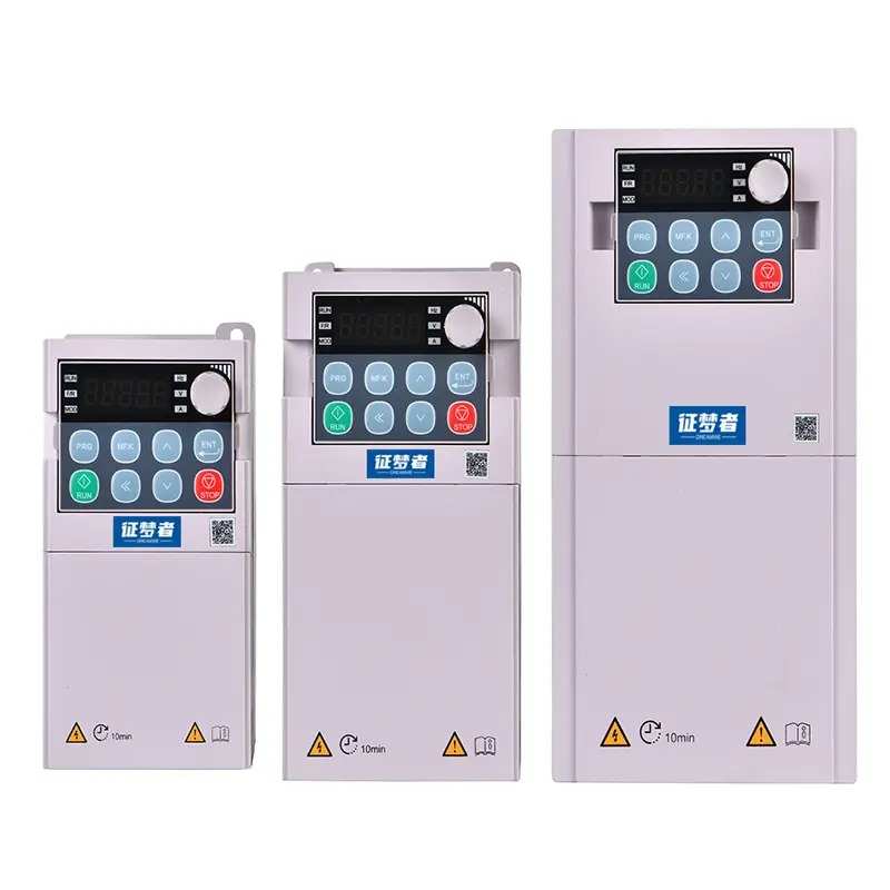
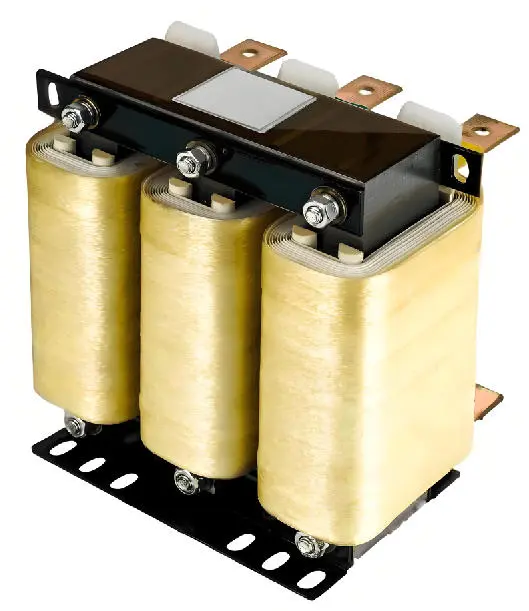
Reasons for Installing Filters on Variable Frequency Drives The primary purpose of installing filters on variable frequency drives is to address electromagnetic interference (EMI) issues generated during operation, while also protecting the stability of the equipment itself and surrounding circuits. The specific reasons are as follows: Suppressing Electromagnetic Interference (EMI) Variable frequency drives regulate motor speed through high-frequency switching (IGBT modules), which generates a large amount of high-frequency harmonics and electromagnetic radiation. These interferences can affect surrounding equipment, such as sensors, PLCs, instruments, and communication devices, through power lines (conducted interference) or through space (radiated interference), resulting in malfunctions, inaccurate measurements, or communication interruptions. Installing a filter can effectively attenuate these high-frequency interferences, preventing them from affecting other equipment. Compliance with Electromagnetic Compatibility (EMC) Standards Many countries and regions have strict standards for electromagnetic radiation from industrial equipment (e.g., EU CE, China GB, etc.). If a VFD is not equipped with a filter, it may fail to meet certification requirements due to excessive electromagnetic radiation, This issue is affecting product compliance and market access. Filters help VFDs meet EMC standards, ensuring legal use of the equipment. Protection of the VFD and Power Grid Noise in the power grid (such as lightning strikes or switching interference from other equipment) may reverse-engineer into the VFD, affecting the stability of its internal circuits (such as control boards or power modules) and even causing failures. Installing an input filter can block grid-side interference from entering the VFD, providing protection; simultaneously, it can also reduce harmonic feedback from the VFD into the grid, preventing pollution of the public power grid. Improving motor operating conditions The high-frequency pulse voltage output by the VFD may generate surge voltages on motor cables, accelerating motor insulation aging, particularly in scenarios with long cables (e.g., exceeding 50 meters). Output filters...
Details
08/04/2025
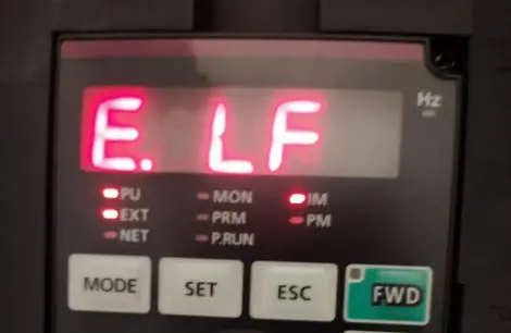
To prevent the variable frequency drive from reporting an E.LF (output phase loss or load fault) fault, measures should be taken from multiple aspects, including equipment installation, parameter settings, and daily maintenance, to reduce the likelihood of the fault being triggered. The following are specific preventive measures: 1. Optimize power supply and wiring to avoid electrical connection issues – Ensure stable power supply: Large fluctuations in the VFD’s input voltage (e.g., exceeding ±10% of the rated value) may cause abnormal current. Install a voltage stabilizer or isolation transformer at the power supply end, especially in industrial environments with unstable power grids. – Standardize wiring and tightening: – The motor cables must be securely connected to the VFD output terminals (U, V, W). Regularly inspect the terminal block screws for loosening (recommended every 3 months) to prevent phase loss due to poor contact. – Motor cables must use copper-core wires that meet specifications, avoiding cables that are too thin (causing excessive line loss) or too long (exceeding the VFD’s maximum allowed cable length, generally recommended ≤50 meters; for longer distances, use thicker cables or reduce the carrier frequency). – Distinguish between input (L1, L2, L3) and output (U, V, W) terminals; reverse connections are strictly prohibited to prevent damage to internal components. 2. Properly configure parameters to match load characteristics – Set the correct motor parameters: Based on the motor nameplate (rated power, voltage, current, speed), accurately input the parameters into the VFD (such as motor rated current, no-load current, pole number, etc.) to ensure that the VFD’s motor protection logic matches the actual load. – Adjust protection thresholds and response times: – Appropriately relax the thresholds for overcurrent and overload protection (but not exceeding 1.2 times the motor’s rated value) to avoid false alarms caused by momentary load fluctuations...
Details
08/04/2025
The variable frequency drive occasionally reports an E.LF fault, which typically indicates a missing phase in the output or a load fault within the drive. The following is a detailed analysis and solution: Abnormal input voltage: When the input voltage to the variable frequency drive is too high, too low, or fluctuates excessively, it may cause abnormal input current, leading to an E.LF fault. Use a multimeter to measure the input voltage and verify if it falls within the VFD’s rated input voltage range. If the voltage is unstable, it is recommended to install a voltage stabilizer. Motor overload: If the motor’s load exceeds its rated value, it can cause current to increase, triggering this fault. The motor’s load is within the rated range, and there are no mechanical obstructions. If so, reduce the load or resolve the mechanical issue. Improper inverter parameter settings: Some inverters require specific parameters to be set based on site conditions, such as overly short acceleration time, overly long deceleration time, or unreasonable low voltage threshold settings, which may cause false alarms. Refer to the inverter manual to verify the relevant parameter settings and adjust them according to actual conditions. Motor or cable fault: Motor winding short circuits, open circuits, or damaged cables, loose connections, etc., can cause three-phase current imbalance, resulting in the VFD reporting an E.LF fault. Check whether the motor winding resistance is normal, whether the cables are damaged or aged, and whether the motor terminal connections are loose. If issues are found, repair or replace the motor, cables, and tighten the terminal connections. Inverter internal faults: Damage to the inverter’s internal components, such as IGBT modules, current detection circuits, or Hall effect sensors, may also cause this fault. If an internal inverter issue is suspected, first inspect the inverter’s internal circuit...
Details
07/21/2025
What are the types of water pumps? There are many types of water pumps. According to different classification criteria (e.g. working principle, application, structure, etc.), the common types of water pumps are as follows: I. Classification according to working principle 1. Centrifugal pumps Characteristics: using impeller rotation to generate centrifugal force to transport liquid, large flow rate, moderate head. Applications: water supply, irrigation, industrial circulation systems (such as IS type, multi-stage centrifugal pumps). 2. Positive displacement pumps Gear pumps: squeeze the liquid through gear meshing, suitable for high viscosity fluids (such as lubricating oil, fuel oil delivery). Screw pumps: screw rotor to promote the liquid, low pulsation, suitable for particle-containing media (sewage treatment, oil industry). Plunger pump / piston pump: high pressure and small flow, used in hydraulic systems, cleaning equipment. 3. Axial flow pump Characteristics: liquid flows in axial direction, large flow, low head. Applications: farmland drainage and irrigation, river drainage (such as large pumping stations). 4. Mixed flow pump Features: between centrifugal pumps and axial pumps, medium flow and head. Applications: urban flood control, agricultural irrigation. 5. Swirl pump Features: impeller generates vortex effect, small flow, high head. Applications: household pressurization, small water supply system. Classification by use 1. Clean water pumps: conveying clean water (such as IS centrifugal pumps, submersible pumps). 2. Sewage pumps: handling liquids containing impurities and fibers (such as WQ submersible sewage pumps). 3. Chemical pumps: corrosion-resistant materials (such as fluorine plastic pumps, stainless steel pumps) for acid and alkali media. 4. Hot water pumps: high temperature resistant design (such as boiler feed pumps, HVAC circulating pumps). 5. Fire pumps: high head, fast response (such as XBD type fire pump). 6. Deep well pumps: long shaft or multi-stage design for deep well water extraction. C. Classification according to installation method 1. Submersible pump: motor...
Details
05/30/2025
Solar inverter is the key equipment in the solar power generation system, its core role is to convert the direct current (DC) generated by solar panels into alternating current (AC) that can be used by household appliances, industrial equipment, etc. In the process of solar power generation, direct current is generated by solar panels after absorbing sunlight, while most of the electrical equipment used in our daily life and production requires alternating current. In the solar power generation process, solar panels absorb sunlight to produce DC power, and most of the electrical equipment used in our daily life and production needs to be AC power, solar inverters take on this “AC/DC conversion” of the important task. In addition, high-quality solar inverters also have a variety of functions, such as maximum power point tracking (MPPT), which can track the optimal working point of solar panels in real time to improve the efficiency of solar energy; it can also realize the grid-connected function, which can input the excess power into the grid; at the same time, some inverters also have a protection function, which can protect the system from over-voltage, overcurrent, and short-circuit, and ensure the stable and safe operation of the solar power generation system. power generation system’s stable and safe operation.
Details