
11/12/2025
Ultimate Guide: How to Identify Brushless vs Brushed Motors When working with electric motors, being able to distinguish between brushless and brushed technologies is essential for proper maintenance, repair, and replacement decisions. This comprehensive guide outlines proven methods to identify motor types through visual inspection, structural analysis, and operational testing. Visual Inspection Techniques for Motor Identification Examining Motor End Construction Key Brushed Motor Features Distinctive metal or plastic end caps designed to house the brushes and commutator assembly Access panels or removable sections for brush inspection and replacement Longer axial length to accommodate the commutator mechanism Visible brush wiring on smaller motor models Identifying Brushless Motor Designs Smooth, uniform end caps without protrusions or access openings Compact overall dimensions with shorter axial profile Integrated Hall sensor connectors on the motor housing Heat sink features on the exterior casing for thermal management Analyzing Terminal Connections Brushed Motor Wiring Patterns Typically feature only two primary power terminals (positive and negative) May include additional terminals for speed control or braking functions Minimal terminal count, generally fewer than 4 connections total Simple wiring configuration without complex connectors Brushless Motor Connection Characteristics Three main power phase terminals (usually labeled U, V, W or A, B, C) Multiple signal terminals (5-8) for Hall effect sensors Higher terminal count, typically 8-12 connections Complex multi-pin connectors rather than individual terminals Structural Analysis Methods Size and Weight Comparison Brushed Motor Physical Traits Larger overall dimensions for equivalent power ratings Heavier rotor assembly containing windings and commutator Higher rotational inertia affecting performance characteristics Bulkier construction with less efficient use of space Brushless Motor Design Advantages Superior power density with smaller footprint for same power output Lighter rotor assembly utilizing permanent magnet technology Lower rotational inertia enabling faster response times Compact, space-efficient construction Thermal Management Features Brushed Motor Cooling Systems Primarily...
Details
11/12/2025
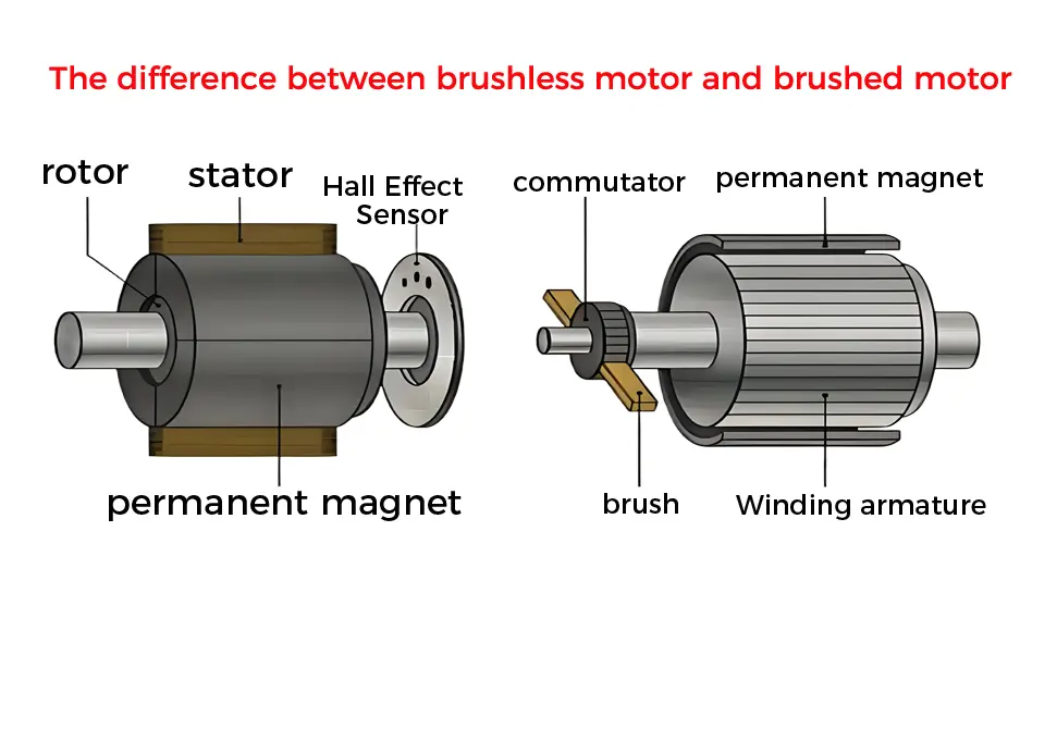
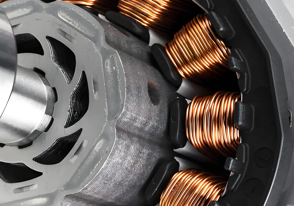
Brushless vs Brushed Motors: Comprehensive Comparison Guide When it comes to electric motor technology, understanding the fundamental differences between brushless and brushed motors is essential for making informed decisions in product design, equipment selection, and system optimization. These two motor technologies offer distinct advantages and disadvantages that significantly impact performance, efficiency, maintenance requirements, and overall cost of ownership. Fundamental Structural Differences Brushed Motor Construction Key Components Incorporates physical carbon brushes and a mechanical commutator Rotor assembly contains wire windings connected to the commutator Stator typically consists of permanent magnets or field windings Brush holders maintain contact pressure between brushes and commutator Brushless Motor Construction Modern Design Features Eliminates physical brushes and mechanical commutators Rotor assembly usually features high-strength permanent magnets Stator contains multiple wire windings arranged in a specific pattern Requires electronic speed controller (ESC) for operation Operational Principles Explained Brushed Motor Functionality Current Flow Process Electrical current travels through brushes into the commutator Commutator segments distribute current to appropriate rotor windings Electromagnetic fields are created in the rotor windings Interaction between rotor and stator magnetic fields produces rotational torque Commutator mechanically reverses current direction as rotor turns Brushless Motor Functionality Electronic Commutation System Position sensors detect rotor orientation (hall effect sensors or sensorless designs) Electronic speed controller processes sensor data ESC sequentially energizes stator windings in optimal sequence Rotating magnetic field is created in the stator Rotor permanent magnets follow the rotating magnetic field Performance Characteristics Comparison Performance Metric Brushed Motors Brushless Motors Energy Efficiency 60-75% typical 85-95% typical Speed Regulation Basic control capability Precise speed control Starting Torque High initial torque Moderate starting torque Maximum RPM Limited by commutator Higher RPM capability Operational Lifespan 1,000-3,000 hours 10,000-20,000+ hours Maintenance Requirements Regular brush replacement Minimal maintenance Noise Production Noticeable operational noise Quiet operation EMI Generation Significant interference Minimal electromagnetic...
Details
11/11/2025
Comprehensive Guide to Motor Shaft Extension Protection Requirements Motor shaft extensions serve as critical power transmission components in industrial machinery, but they also present significant safety hazards due to their rotating nature. Proper protection of these components is essential for ensuring workplace safety, preventing accidents, and maintaining equipment reliability. This comprehensive guide outlines the key requirements for effective motor shaft extension protection systems. Essential Safety Requirements for Motor Shaft Protection Protection Coverage Specifications Complete Enclosure Requirements Protective devices must fully enclose all rotating elements including shaft extensions, keyways, shaft ends, and couplings Total coverage eliminates exposure of moving parts that could cause injury Safety distance calculations must account for maximum shaft deflection during operation Protection must extend beyond the immediate shaft area to include associated rotating components Structural Integrity Standards Protective barriers must withstand minimum impact forces as specified in ISO 13857 Materials must maintain structural integrity under expected operating conditions Design must prevent accidental dislodgement during machine operation Load-bearing capacity should exceed anticipated forces from normal operation and maintenance activities Access Prevention Measures Physical barriers must prevent finger, hand, or tool access to hazardous areas openings or gaps must not exceed 8mm for finger protection Perimeter protection should extend to prevent reaching around, under, or over the guard Design must account for human factors engineering principles to prevent unintentional access Protective Device Classification and Selection Fixed Protective Systems Permanent Barrier Solutions Bolted or welded enclosures requiring tools for removal Ideal for applications with minimal maintenance requirements Materials selection based on environmental conditions and durability needs Design should facilitate visual inspection without removal Adjustable and Removable Protection Quick-Access Design Features Hinged or sliding mechanisms for maintenance access Quick-release fasteners that maintain security during operation Position indicators to confirm proper closure Interlocking capabilities to prevent operation when open Interlocking Protection Systems...
Details
11/11/2025
Key Factors Affecting Electric Motor Stability and Performance Motor stability is a critical factor that directly impacts equipment performance, operational efficiency, and service life in industrial applications. Understanding the various elements that influence motor stability is essential for maintenance professionals, engineers, and facility managers. In this comprehensive guide, we explore the primary factors affecting motor stability and provide insights into optimizing motor performance. Electrical System Factors Power Supply Quality Voltage fluctuations and instability directly impact motor output power consistency Frequency variations significantly influence motor speed regulation and stability Harmonic distortion in power supplies causes additional losses, heating, and premature wear Three-phase voltage imbalance leads to motor overheating, torque ripple, and reduced efficiency Motor Design Parameters Winding configuration and distribution affect magnetic field uniformity and torque production Number of poles and stator design influence rotational speed stability and performance characteristics Insulation class rating determines the motor’s ability to withstand temperature variations Rotor construction impacts starting torque, running efficiency, and overall operational stability Control System Performance Variable Frequency Drive (VFD) technology and control algorithms directly affect speed regulation Feedback system precision and response time influence dynamic performance Control parameter optimization is critical for achieving desired performance characteristics Protection system design prevents damage from electrical faults and abnormal operating conditions Mechanical System Factors Load Characteristics and Requirements Load type classification (constant torque, variable torque, constant power) Load variation rates and impact load handling capability Starting and braking torque requirements during transient operations Load-motor matching for optimal performance and efficiency Installation and Alignment Quality Precise motor-to-load alignment minimizes vibration and premature wear Proper bearing installation and lubrication ensure smooth operation Foundation stiffness and vibration isolation measures reduce external influences Coupling selection and installation affect torque transmission efficiency Mechanical Resonance Considerations System natural frequency identification and management Critical speed avoidance through proper design and operation...
Details
11/11/2025
Why Motor Inverters Need Skip Frequency Settings: A Comprehensive Guide If you work with electric motors and variable frequency drives (VFDs), you may have encountered the term “skip frequencies.” But why are these settings important, and how do they affect motor performance? In this article, we’ll explore the science behind skip frequencies and why they’re essential for optimal motor operation. Understanding Skip Frequencies in Motor Control Skip frequencies, also known as avoidance frequencies or jump frequencies, are specific points within an inverter’s operating range that the system is programmed to bypass. When a motor accelerates or decelerates, the VFD automatically skips these predetermined frequencies rather than operating at them continuously. The Critical Role of Skip Frequencies Preventing Mechanical Resonance The primary reason for implementing skip frequency settings is to avoid a phenomenon known as mechanical resonance. Every motor and the equipment it powers has a unique natural vibration frequency determined by factors like: Physical dimensions and material properties Mounting configuration Load characteristics System rigidity When a motor operates at or near this natural frequency, resonance occurs, creating a feedback loop that amplifies vibrations throughout the system. Consequences of Uncontrolled Resonance Without proper skip frequency settings, resonance can lead to numerous problems: Excessive noise pollution in the workplace Accelerated wear on bearings, gears, and other mechanical components Premature equipment failure and increased maintenance costs Reduced precision in manufacturing processes Safety hazards from excessive vibration Potential damage to structural components Equipment-Specific Applications Certain types of machinery are particularly susceptible to resonance issues and therefore benefit greatly from skip frequency settings: Precision machine tools requiring tight tolerances Elevators and escalators where smooth operation is critical Centrifuges and high-speed rotating equipment Industrial fans and blowers Pumps and compressors Conveyor systems and material handling equipment Implementing Effective Skip Frequency Settings Identifying Critical Frequencies To establish...
Details
11/10/2025
DC Braking for Inverters: Applications, Settings, and Best Practices Understanding DC Braking Technology DC braking is a critical function in variable frequency drives (VFDs) that applies direct current to the motor stator windings, creating a stationary magnetic field. This generates braking torque on the rotating rotor, enabling precise and rapid motor stopping when needed. Key Applications for DC Braking 1. Precision Stopping Scenarios Material handling systems: Conveyor belts requiring accurate positioning Elevator systems: Precise floor leveling and emergency stopping CNC machinery: Accurate spindle positioning for machining operations Packaging equipment: Registration control for label application 2. Rapid Deceleration Requirements Centrifuges: Medical and industrial applications needing quick stops Pump systems: Emergency shutdown for fluid control Fan applications: Rapid air flow reduction in critical environments Printing presses: Quick changeover between production runs 3. Anti-Creep Applications Crane and hoist systems: Preventing load drift when stationary Inclined conveyors: Stopping material slide on angled surfaces Elevator doors: Maintaining position during power interruptions Assembly lines: Precise stopping during production processes 4. Mechanical Brake Replacement Automated guided vehicles: Reducing maintenance on mechanical brakes Textile machinery: Eliminating wear on friction components Food processing equipment: Improving hygiene by reducing mechanical parts Robotics systems: Enhancing positioning accuracy and reliability Essential Parameter Configuration 1. Activation Settings DC brake start frequency: Typically 2-10Hz below rated speed Brake activation trigger: Frequency-based, time-based, or external signal Transition smoothness: Adjust ramp times to prevent mechanical shock 2. Braking Intensity Parameters DC brake voltage level: 10-30% of motor rated voltage Braking current magnitude: 20-80% of motor rated current Current rise/fall times: 0.1-2 seconds for smooth transitions 3. Protection Parameters Overcurrent threshold: Typically 150-200% of rated current Thermal protection: Monitor inverter and motor temperatures Brake duration limit: Prevent overheating with time restrictions 4. Application-Specific Adjustments Stop accuracy tolerance: 0.1-1 revolution depending on application Repeatability settings: For consistent stopping...
Details

11/10/2025
How to Fix Corrupted Inverter Parameters: Complete Troubleshooting Guide If your inverter parameters have become corrupted or disrupted, this comprehensive guide will help you diagnose and resolve the issue efficiently. Common Causes of Parameter Corruption 1. Power-related Issues Voltage fluctuations or surges: Electrical instability can disrupt parameter storage Improper shutdown procedures: Powering off without proper shutdown sequence Battery backup failure: On units with memory backup batteries 2. User Error Accidental parameter changes: Unintentional modification of critical settings Incorrect programming: Entering wrong values during setup Unauthorized access: Lack of parameter modification controls 3. Hardware Problems Memory chip failure: Issues with the non-volatile memory storage Mainboard malfunction: Circuitry problems affecting parameter retention Connection issues: Loose cables disrupting communication 4. Environmental Factors Electromagnetic interference: From nearby high-power equipment Extreme temperatures: Operating outside recommended temperature range Humidity or moisture: Affecting internal components Step-by-Step Parameter Recovery Process 1. Initial Assessment Document current parameters: Record all visible settings before making changes Check for error codes: Note any displayed error messages Verify power supply: Ensure stable voltage input 2. Parameter Restoration Methods Method 1: Factory Reset 1. Access the parameter setting menu 2. Locate "Factory Reset" or "Parameter Initialization" function 3. Confirm the reset operation (this will erase all custom settings) 4. Restart the inverter and reconfigure as needed Method 2: Manual Parameter Reconfiguration Consult the manufacturer’s manual for default parameter values Re-enter motor specifications (voltage, current, frequency ratings) Configure control modes and operating parameters Set up protection functions and limits Method 3: Backup Restoration Upload previously saved parameter file if available Use manufacturer-provided software for parameter restoration Verify all critical parameters after restoration 3. Verification and Testing Perform no-load test run to check basic functionality Gradually apply load and monitor performance Verify all protection functions are working correctly Document final parameter settings for future reference Preventive...
Details
11/10/2025
How to Fix Inverter Display Flickering: Troubleshooting Guide If you’re experiencing display flickering on your inverter, you’re not alone. This common issue can be caused by several factors, but most can be resolved with some basic troubleshooting. Common Causes of Inverter Display Flickering 1. Power Supply Problems Unstable voltage input: Verify that the input voltage matches the inverter’s specifications Loose power connections: Check all power cables for secure connections Damaged power filter: Test and replace if necessary 2. Connection Issues Loose display cable: Ensure the cable connecting the display to the main board is properly seated Corroded connectors: Clean all connectors with appropriate contact cleaner Electromagnetic interference: Move the inverter away from motors, transformers, or other high-power devices 3. Hardware Failures Faulty display panel: Test with a replacement display if available Defective driver circuit: Inspect for damaged components on the driver board Main board issues: Contact a professional technician for diagnosis and repair 4. Configuration Problems Incorrect display settings: Reset to factory default settings Contrast or brightness issues: Adjust display parameters for optimal visibility Step-by-Step Troubleshooting Process Check power supply with a multimeter to ensure stable voltage Inspect all connections for tightness and corrosion Eliminate external interference by moving the inverter to a different location Reset display settings to factory defaults Test with replacement components if possible (display, cables) Contact professional repair service if the issue persists Preventive Maintenance Tips Regularly inspect and clean all connections Keep the inverter in a clean, dry environment Avoid overloading the inverter beyond its rated capacity Schedule periodic professional maintenance checks By following these troubleshooting steps, you can often resolve display flickering issues without extensive repairs. If you need further assistance, please provide your inverter’s make, model, and any error codes displayed.
Details
11/07/2025
VFD Braking Unit Selection Guide: Complete Technical Reference Introduction Variable Frequency Drives (VFDs) are essential components in modern industrial automation, providing precise control of motor speed and torque. However, when dealing with high-inertia loads or frequent braking requirements, proper selection of braking units and resistors becomes critical to ensure system reliability and performance. I. When to Use a Braking Unit Before selecting a braking unit for your VFD system, it’s important to determine if one is actually needed. The following scenarios typically require braking units: High-Inertia Loads Applications such as centrifuges, large fans, and water pumps generate significant regenerative energy during deceleration that must be dissipated. Frequent Start-Stop Operations Equipment like cranes, elevators, and conveyors that require frequent starting, stopping, or reversing benefit from proper braking systems. Rapid Deceleration Requirements When process requirements specify deceleration times less than 1/3 of the natural stopping time, braking units become necessary. Gravity-Loaded Applications Vertical movement systems such as lifts and cranes continuously generate regenerative energy when lowering loads. Situations Where Braking Units May Not Be Needed: Low-inertia loads (small fans, pumps) Applications with infrequent braking requirements Systems with adequate natural deceleration time Small-power VFDs with sufficient built-in braking capacity II. Calculation Methods for Braking Unit Selection 1. Braking Power Calculation General Formula: P = (J × Δω²) / (2 × t) × η Where: J = Moment of inertia (kg·m²) Δω = Angular velocity change (rad/s) t = Deceleration time (s) η = Mechanical efficiency Special Formula for Lifting Equipment: PE = G × V × 9.81 PW = PE × (1 - n) Where: PE = Power from descending potential energy G = Weight of load (kg) V = Descending speed (m/s) PW = Braking power required n = Internal loss coefficient (typically 20%) 2. Braking Resistor Calculations Resistance Calculation: R =...
Details
11/04/2025
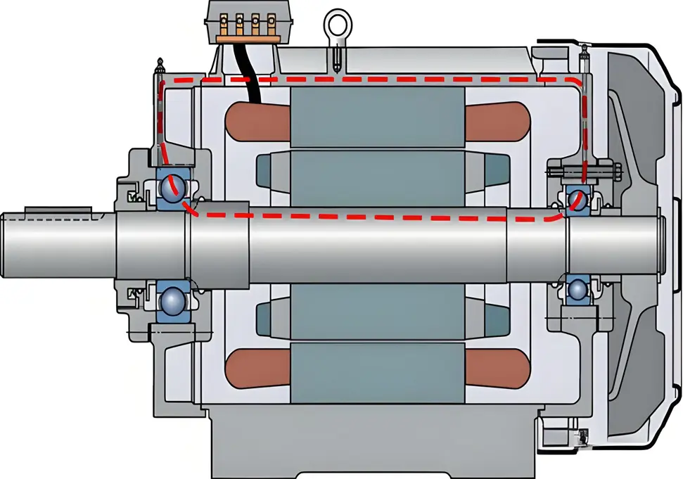
Shaft Current in Electric Motors: Causes, Effects, and Prevention Strategies Introduction Shaft current in electric motors is a critical issue that can lead to premature equipment failure, increased maintenance costs, and unexpected downtime. This comprehensive guide explores the various causes of shaft current, its detrimental effects on motor performance, and effective prevention strategies to ensure reliable and efficient motor operation. Understanding Shaft Current Shaft current refers to the flow of electrical current along the rotating shaft of an electric motor. This current typically travels from one end of the shaft to the other, or between the shaft and other motor components such as bearings and the motor frame. While motors are designed to be electrically neutral, various factors can create potential differences that initiate this unwanted current flow. Primary Causes of Shaft Current 1. Magnetic Circuit Asymmetry Stator core irregularities: Manufacturing imperfections in stator core laminations Rotor misalignment: Eccentricity between rotor and stator creating uneven air gaps Core saturation issues: Localized magnetic saturation due to design flaws or overloading Winding faults: Short circuits or ground faults causing magnetic field distortions 2. Electrostatic Induction Triboelectric charging: Friction between shaft and bearings generating static electricity Belt-driven systems: Charge generation through belt-pulley friction Oil film breakdown: High-speed operation causing lubricant film breakdown Environmental conditions: Low humidity environments promoting static accumulation 3. Electromagnetic Induction Effects Variable frequency drive (VFD) harmonics: High-frequency components inducing shaft voltages Flux cutting: Rotating shaft cutting through magnetic fields Capacitive coupling: Voltage transfer between windings and shaft Common-mode voltages: Voltage imbalances in three-phase systems 4. Grounding System Problems Improper grounding design: Inadequate or inconsistent grounding practices Multiple grounding points: Different potential levels at various grounding locations Ground loop formation: Current circulation within grounding systems Ground potential differences: Voltage variations between different earth points 5. Power Quality Issues Voltage harmonics: Non-sinusoidal...
Details
11/04/2025
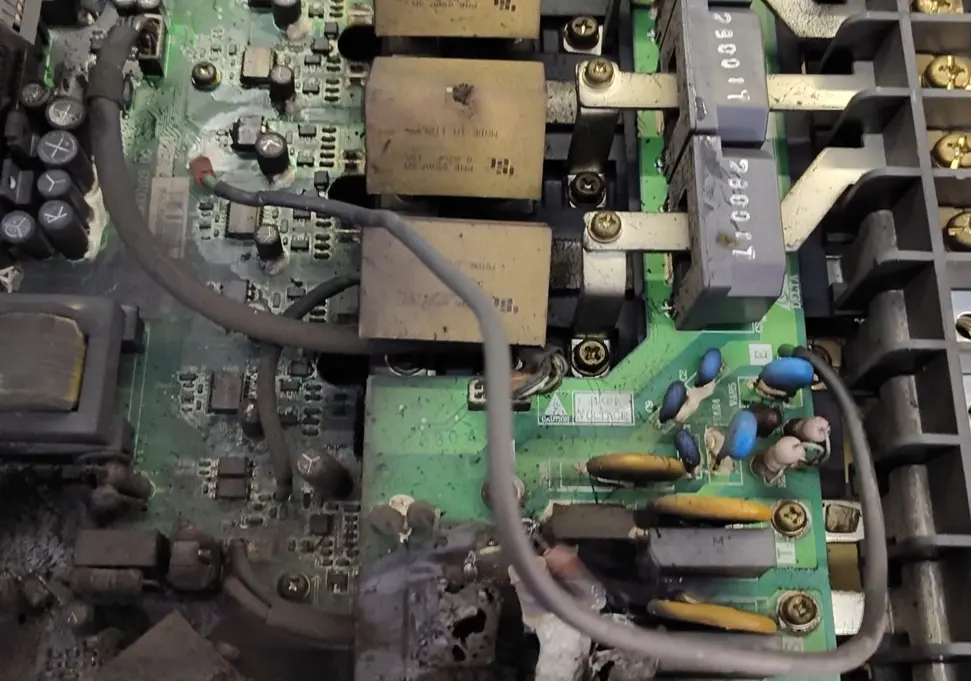
How to Handle Variable Frequency Drive (VFD) Failure: A Comprehensive Troubleshooting Guide Introduction Variable Frequency Drive (VFD) failure can be a costly and dangerous issue in industrial settings. When a VFD malfunctions or “fails catastrophically,” it can lead to unplanned downtime, equipment damage, and potential safety hazards. This comprehensive guide outlines the immediate steps to take when facing a VFD failure, how to diagnose the root cause, and preventive measures to avoid future issues. Immediate Safety Response Power Isolation Cut power supply: Immediately shut off the main power supply to the VFD Confirm de-energization: Verify that all power indicators are off before proceeding Lockout/tagout: Use lockout/tagout procedures to prevent accidental re-energization Hazard Assessment Evaluate environment: Check for smoke, fire, or hazardous fumes Use protective equipment: Wear appropriate PPE including gloves, safety glasses, and protective clothing Ventilate area: Ensure proper ventilation if smoke or fumes are present Fire safety: Have fire extinguishing equipment nearby if needed Area Securing Post warning signs: Place warning signs around the affected area Restrict access: Prevent unauthorized personnel from approaching the faulty equipment Notify personnel: Inform supervisors, maintenance teams, and safety officers Post-Failure Assessment Visual Inspection External examination: Look for signs of physical damage, burns, or deformation Check for blown fuses or tripped circuit breakers Inspect cable connections for damage or overheating Internal inspection (only after complete cooling): Look for capacitor swelling or explosion Check for burnt components or PCB damage Inspect cooling fans and heatsinks for blockages Documentation Photographic evidence: Take detailed photos of the failure from multiple angles Event timeline: Document the sequence of events leading to failure Data collection: Gather any available fault codes or diagnostic information Environmental factors: Note environmental conditions (temperature, humidity, etc.) Root Cause Analysis Electrical System Checks Power quality testing: Check for voltage fluctuations, harmonics, or transients Grounding verification: Verify...
Details
11/04/2025
How to Measure Variable Frequency Drive (VFD) Output Frequency: A Comprehensive Guide Introduction Variable Frequency Drives (VFDs) are essential components in modern industrial motor control systems. Accurate measurement of a VFD’s output frequency is critical for system commissioning, performance optimization, and troubleshooting. This guide explores various methods for measuring VFD output frequency, their advantages and limitations, and important considerations for accurate results. 1. Using a Digital Frequency Meter Digital frequency meters provide a direct and precise measurement method: Contact Measurement Method Connect the frequency meter probes to the VFD output terminals (usually labeled U, V, W) Ensure proper insulation and safety precautions Read the frequency directly from the digital display Non-Contact Measurement Method Use a clamp-on frequency meter around one of the VFD output cables This method eliminates the need for direct electrical connection Ideal for quick checks and troubleshooting Advantages: High accuracy, easy to use, real-time measurement Considerations: Select a meter compatible with PWM waveforms 2. Oscilloscope Measurement Technique Oscilloscopes offer both frequency measurement and waveform analysis: Connect the oscilloscope probe to the VFD output terminals Set appropriate voltage and time divisions on the oscilloscope Use the built-in frequency measurement function or manually calculate using the waveform period Observe waveform distortion and harmonic content Advantages: Provides visual waveform analysis, identifies harmonic issues Applications: Particularly useful during system commissioning and troubleshooting 3. PLC and Control System Integration Modern control systems can monitor VFD frequency through communication: Establish communication between PLC and VFD using protocols like Modbus, Profinet, or Ethernet/IP Configure appropriate register addresses for frequency data Display real-time frequency on HMI panels or monitoring software Implement data logging for historical analysis Advantages: Remote monitoring, automated data collection, integration with control logic Implementation: Requires proper communication configuration and programming 4. Motor Speed Calculation Method When direct VFD measurement isn’t possible, calculate...
Details