

09/09/2025
In the speed control technology for AC motors using frequency converters, V/F Control (Voltage/Frequency Control) and Vector Control (also known as Field-Oriented Control, FOC) are two of the most widely applied solutions. They rely on distinct control principles and differ significantly in speed regulation performance, application scenarios, structural complexity, and other core dimensions. This article details their differences across 5 key dimensions to help you understand their positioning and selection logic. 1. Core Control Principle Differences (Fundamental Distinction) The control principle is the root difference between the two technologies, directly determining all subsequent performance outcomes: V/F Control: Open-Loop/Semi-Closed-Loop Control Based on “Steady-State Experience” Its core logic is to maintain a constant ratio of the motor’s stator voltage to supply frequency (V/F ratio). For an AC motor, the stator flux (Φ) follows the simplified formula: Φ ≈ U/(4.44fN₁) (where U = stator voltage, f = frequency, N₁ = number of stator turns). When f changes, only by keeping the U/F ratio constant can we avoid flux saturation (which causes motor overheating) or insufficient flux (which leads to torque loss). During operation, the frequency converter only outputs the corresponding voltage based on the “set frequency”—it does not directly detect or control the motor’s critical physical parameters, such as rotor speed, flux, or torque. This is essentially “control based on empirical formulas,” operating as an open-loop system or a simple semi-closed-loop system (some V/F control setups with PG cards add speed feedback to correct frequency, but this does not alter the core V/F logic). Vector Control: Closed-Loop Control Based on “Dynamic Modeling” Its core logic is to decompose the AC motor’s stator current into two independent components—”excitation current” and “torque current”—and control them separately, simulating the speed regulation principle of DC motors (DC motors achieve precise torque and speed control by independently adjusting excitation winding and armature winding currents)....
Details
09/09/2025
What is Inverter Vector Control? Inverter Vector Control, also known as Field-Oriented Control (FOC), is a high-precision variable-frequency speed regulation technology based on motor electromagnetic theory. It “decouples” the complex current components in asynchronous or synchronous motors and converts them into independent control variables similar to those in DC motors. This enables precise, rapid adjustment of motor speed and torque, addressing the shortcomings of traditional V/F control in dynamic response, low-speed torque, and speed regulation accuracy. I. Core Principle: “Decoupling” and “Field Orientation” To understand vector control, you first need to grasp its core logic: transforming the complex control of AC motors into the simple control of DC motors. The specific principle breaks down into three key steps: Current Decomposition (Decoupling)The stator current of an AC motor comprises two core components: Excitation current component (Id): Used solely to establish the motor’s air-gap magnetic field and has no connection to motor speed; Torque current component (Iq): Directly determines the motor’s output torque and is proportional to load demand.Through mathematical algorithms (such as Clark transformation and Park transformation), vector control decomposes the three-phase stator current into these two independent DC components. This achieves separate control of the “magnetic field” and “torque” (known as “decoupling”). Field OrientationThe direction of the motor’s rotor magnetic field serves as the “reference coordinate axis” (commonly called the d-axis), while the torque current component is controlled along the direction perpendicular to the magnetic field (q-axis). This “orientation” ensures the two current components do not interfere with each other—similar to the independent regulation of the “excitation winding” and “armature winding” in a DC motor. Closed-Loop Feedback RegulationA motor encoder (or sensorless algorithm) detects real-time signals like speed and rotor position. After comparing these signals with target values, the system dynamically adjusts the output of Id and Iq to ultimately achieve...
Details

09/09/2025
What is V/F Control of Inverters? V/F Control (Voltage/Frequency Control) of inverters is one of the most basic and widely used variable-frequency speed regulation methods. Its core principle is to synchronously adjust the output voltage (V) in a fixed proportion while changing the motor’s supply frequency (f) to regulate speed. This ensures the motor’s air-gap flux remains essentially constant, preventing magnetic circuit saturation or insufficient torque and enabling stable speed regulation. I. Core Logic of V/F Control: Why “Synchronously Regulate V and F”? To understand V/F control, you first need to grasp the motor’s core operating principle — the motor’s air-gap flux (Φ) is directly linked to voltage (V) and frequency (f). This relationship can be simplified using the formula for the induction electromotive force in the motor’s stator winding:E ≈ 4.44 × f × N × Φ(Where E is the stator-induced electromotive force, approximately equal to the supply voltage V; N is the number of winding turns, an inherent parameter of the motor) When the frequency f decreases (motor decelerates): If the voltage V stays unchanged, the flux Φ will increase (per the formula), causing the motor’s magnetic circuit to saturate. This leads to a sharp rise in excitation current, which can overheat the motor, create noise, or even cause damage. When the frequency f increases (motor accelerates): If the voltage V remains unchanged, the flux Φ will decrease, resulting in a significant drop in the motor’s output torque. This leaves the motor unable to drive the load (a phenomenon commonly called “flux loss”). Thus, the core goal of V/F control is to maintain a constant V/f ratio by “adjusting V in a fixed proportion with F”. This keeps the flux Φ essentially unchanged, allowing the motor to output stable torque at different speeds. II. Key Parameter of V/F Control: The V/f Curve The...
Details
09/08/2025
How to Improve the Speed Regulation Accuracy of V/F Control? The speed regulation accuracy of V/F control (Voltage/Frequency Control) is limited by its open-loop control characteristics (no speed feedback) and variations in motor parameters. However, it can be significantly enhanced through the following technical methods: I. Core Optimization Measures Incorporate Speed Feedback (Closed-Loop V/F Control)Install an encoder or Hall sensor on the motor shaft to real-time detect the actual speed, compare it with the target speed, and dynamically correct the output frequency via PID regulation. This reduces the speed error from ±2%–5% (in open-loop mode) to ±0.5%–1%.Suitable for scenarios with moderate accuracy requirements (e.g., conveyor synchronization), and its cost is lower than that of vector control. Optimize V/F Curve Design Segmented V/F Curve: Set different V/F ratios for distinct frequency ranges based on motor characteristics (e.g., increase voltage compensation in the low-frequency range and moderately reduce it in the high-frequency range) to minimize nonlinear errors. Custom Curve Calibration: Manually correct the voltage value at specific frequency points through no-load or load tests to offset individual motor differences (e.g., deviations caused by varying winding resistance or iron core losses). Dynamic Parameter Compensation Temperature Compensation: Detect the temperature of the motor windings and real-time adjust the resistance voltage drop model (copper loss increases as temperature rises) to prevent insufficient torque at low frequencies or magnetic flux saturation at high frequencies. Load Compensation: Estimate the impact of load fluctuations on speed by detecting changes in output current, and automatically fine-tune the frequency (e.g., slightly increase the frequency when the load increases to maintain stable speed). Suppress Grid and Load Interference Install an input filter to reduce the impact of grid voltage fluctuations on the output voltage, avoiding deviations in the V/F ratio caused by unstable voltage. For shock loads (e.g., mixers), extend the acceleration or deceleration...
Details
09/08/2025
What Is the Principle of V/F Control for Inverters? V/F control (Voltage/Frequency Control) is the most fundamental speed regulation method for inverters. Its core principle involves maintaining a constant ratio between the motor’s stator voltage (V) and supply frequency (F), which ensures the motor’s air-gap magnetic flux remains essentially stable—ultimately enabling smooth speed regulation. The specific principle can be broken down into the following key points: Core of Constant Magnetic Flux: According to motor theory, the motor’s air-gap magnetic flux is proportional to the stator voltage and inversely proportional to the frequency (Φ ∝ V/F). Maintaining a constant V/F ratio prevents magnetic flux saturation (during overvoltage) or insufficient magnetic flux (during undervoltage), thus ensuring stable motor output performance. Low-Frequency Compensation: In practical applications, additional voltage compensation (commonly referred to as “torque boost”) is necessary in the low-frequency range (e.g., below 5Hz). This compensates for magnetic flux attenuation caused by voltage drops across the motor’s stator resistance, ensuring the motor still delivers sufficient torque at low speeds. Implementation of Speed Regulation: Motor speed is adjusted by modifying the output frequency (F), as speed is directly proportional to frequency (n ∝ F). Simultaneously, the output voltage (V) is adjusted proportionally to maintain the preset V/F ratio, allowing for smooth speed regulation across a wide range. This control method boasts a simple structure and low cost, making it ideal for scenarios like fan and pump systems where high dynamic response is not required. However, it has relatively limited performance in terms of speed regulation accuracy and low-speed torque.
Details
09/08/2025
Applications of V/F Control Inverters V/F control (Voltage/Frequency Control) is one of the most fundamental and classic control methods for inverters. Its core principle involves maintaining a constant ratio between the motor stator voltage and supply frequency (V/F ratio), ensuring the motor’s air-gap flux remains essentially unchanged. This enables smooth speed regulation of the motor. Due to its simple structure, low cost, high reliability, and minimal dependence on motor parameters, V/F control inverters are widely used in scenarios where speed regulation accuracy and dynamic response requirements are not stringent, but cost-effectiveness and stability are critical. I. Core Application Scenarios Based on load characteristics and industry requirements, typical applications of V/F control inverters can be categorized as follows: 1. Fan Systems (Primary Application) Fan loads are characterized by load torque being proportional to the square of the speed (T∝n²). They require low starting torque, have no strict dynamic response needs during speed adjustment, and do not require frequent starts/stops or reversals—making them ideal for V/F control. Key Applications: Industrial ventilation fans: Used in factory workshops, power plant boilers, and chemical plants to regulate air volume, achieving 20-40% energy savings compared to traditional damper control. HVAC system fans: Central air conditioning blowers and fresh air fans that adjust speed based on indoor temperature to balance comfort and energy efficiency. Smoke and dust extraction fans: Fire safety exhaust systems in buildings and dust removal fans in mines/tunnels that maintain stable airflow to prevent overload. 2. Pump Systems (Major Application Area) Similar to fans, pump loads exhibit square-law torque characteristics (T∝n²). Their primary requirement is flow control with low speed accuracy demands, perfectly matching V/F control’s advantages of low cost and stable regulation. Key Applications: Industrial circulation pumps: Cooling water systems in power plants, steel mills, and chemical facilities that adjust speed to...
Details
09/05/2025
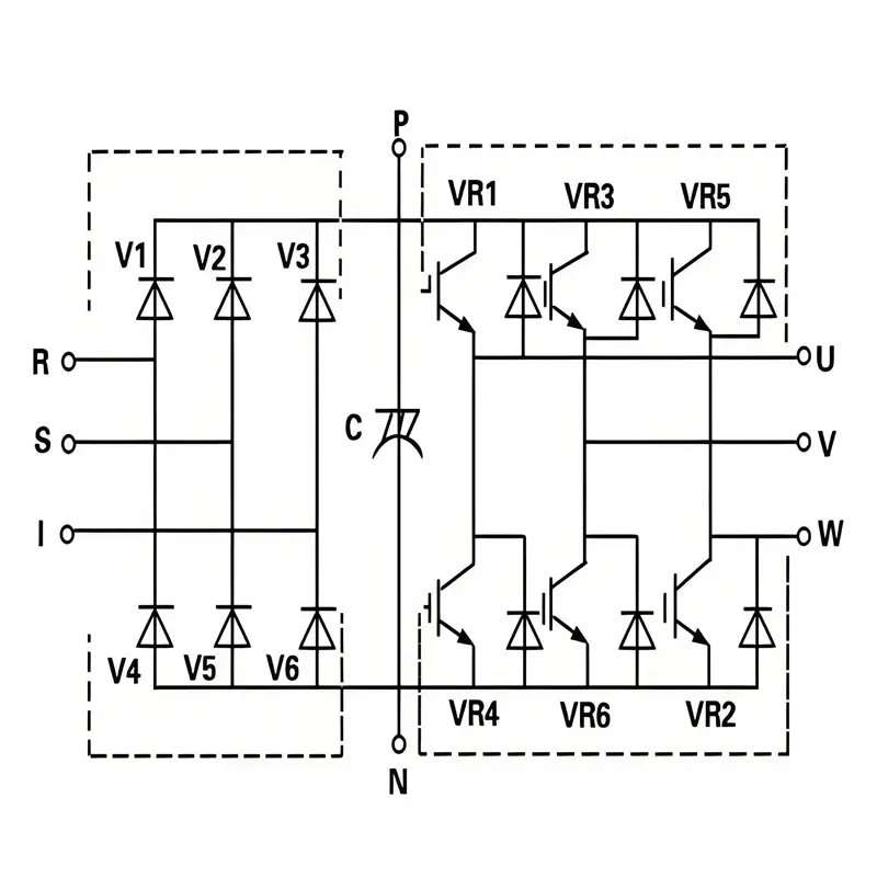
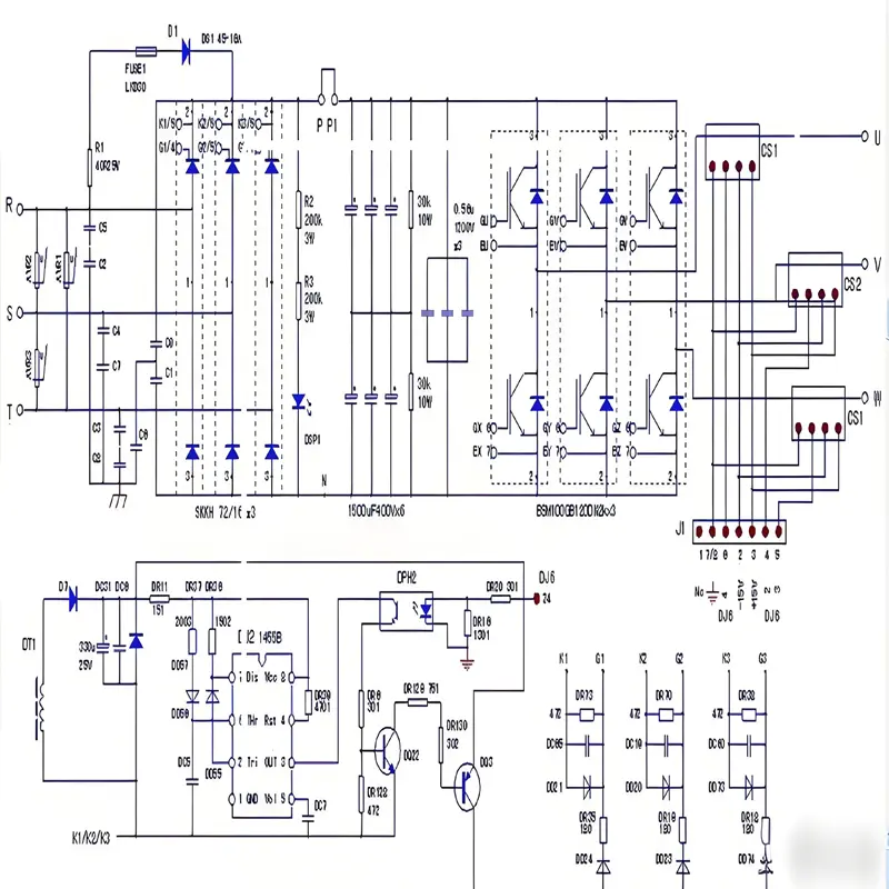
How Does Inverter Circuit Achieve Variable Frequency? VFD Principles, Applications & Troubleshooting In the variable frequency drive (VFD) industry, the inverter circuit is the core component that converts stable DC power (from rectification and filtering) into AC power with adjustable frequency and voltage. This variable frequency capability directly determines the motor’s speed control precision, energy efficiency, and adaptability to different loads—whether for a 0.75kW fan or a 400kW elevator traction motor. The realization of variable frequency is not a single-step process but a systematic collaboration of “control signals, power switching, waveform synthesis, and feedback adjustment.” This article details the core principles, industry-specific applications, and troubleshooting methods, tailored to the needs of industrial electrical engineers, VFD maintenance personnel, and equipment buyers. I. Fundamental Precondition: Stable DC Power Supply from Rectification & Filtering Before the inverter circuit can adjust frequency, it first requires a consistent DC input—fluctuations in DC voltage will directly distort the output frequency and voltage. This “DC foundation” is established through two key stages: 1. Rectification: Converting AC to Pulsating DC Low-power VFDs (≤0.75kW): Use a diode bridge rectifier (4 diodes for single-phase, 6 for three-phase). Diodes’ unidirectional conductivity converts sinusoidal AC (e.g., 220V/380V grid power) into pulsating DC. For a 380V three-phase input, the peak pulsating DC voltage is approximately 540V. Medium-to-high-power VFDs (≥11kW): Adopt thyristor rectification or IGBT PWM rectification. These designs not only rectify AC to DC but also actively regulate the DC-side voltage (e.g., maintaining 540V ±2% stability) and reduce grid harmonic interference (complying with IEC 61000-3-2 Class A standards). 2. Filtering: Smoothing Pulsating DC The rectified DC contains significant ripples (6x the grid frequency for three-phase rectification). A DC-link filter (large-capacity electrolytic capacitors for small power, or capacitor-inductor combinations for high power) eliminates these ripples: For a 15kW VFD, two 4700μF/450V electrolytic capacitors are typically connected in parallel, reducing voltage ripple from...
Details
09/05/2025
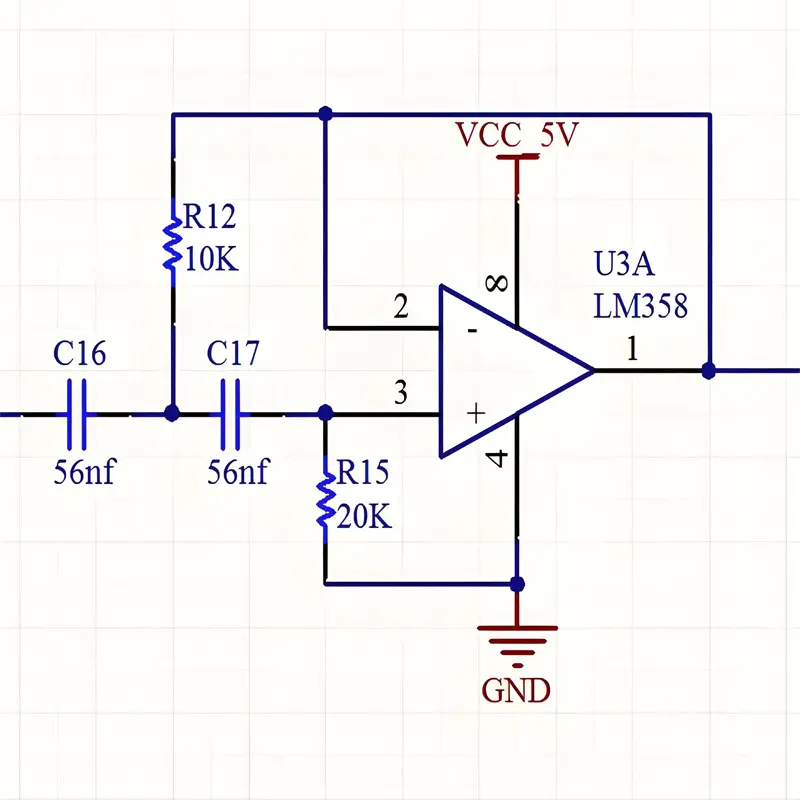
How to Smooth Voltage Fluctuations in Inverters? Filter Circuit Types & VFD Applications In the inverter (Variable Frequency Drive, VFD) industry, stable DC-link voltage is the core guarantee for reliable motor operation and precise speed control. Voltage fluctuations in the DC-link—caused by the pulsating output of the rectifier circuit or sudden load changes—can trigger VFD overvoltage/undervoltage protection, damage IGBT modules, or lead to motor speed instability. As the “voltage stabilizer” of inverters, filter circuits play a critical role in “smoothing” these fluctuations. This article focuses on inverter-specific filter solutions, their working principles, and practical application guidelines, tailored to the needs of industrial electrical engineers, VFD maintenance personnel, and equipment buyers. I. Inverter-Specific Filter Solutions: Matching Scenarios to Performance Needs Inverters vary widely in power rating (from 0.75kW to 400kW+) and load characteristics (light/heavy, constant/variable), so filter circuit selection must align with application scenarios. Below are the three most common filter schemes in the VFD industry, along with their “smoothing” mechanisms and on-site adaptation: 1. Capacitor Filter: The Core Solution for Medium-and Small-Power VFDs Capacitor filters are used in 90% of medium-and small-power inverters (1.5kW–55kW) (e.g., VFDs for fans, water pumps, and conveyors). They act as “electrical energy reservoirs” to smooth DC-link voltage through rapid charging and slow discharging. How It “Smooths” Fluctuations After three-phase rectification (380V AC input), the raw DC output has 6x grid frequency pulsations (≈300Hz), with a voltage fluctuation range of ±30V (peak DC ≈540V). A large-capacity electrolytic capacitor (typically 2200μF–10,000μF/450V) is connected in parallel across the DC-link: When the rectified voltage rises above the capacitor’s current voltage, the capacitor charges quickly to store energy, “catching” the voltage peak. When the rectified voltage drops below the capacitor’s voltage, the capacitor discharges slowly to supplement the DC-link, filling voltage troughs. Result: Voltage fluctuations are reduced from ±30V to ±5V, and...
Details
09/05/2025
The Role of Rectifier Circuits in Inverters In the overall architecture of a variable frequency drive (VFD), the rectifier circuit serves as the primary core component for energy conversion. Its key function is converting externally input alternating current (AC) into direct current (DC), providing a stable DC power foundation for subsequent inversion processes. Without this AC-DC conversion, inverters cannot accurately control output frequency and voltage, making rectification the first critical step in the “AC-DC-AC” conversion topology. I. Core Functions of Rectifier Circuits in Inverters An inverter’s operational process can be simplified into three main stages: rectification → filtering → inversion. The rectifier circuit’s functions focus on converting AC to usable DC, with two primary responsibilities: 1. AC-DC Energy Conversion (Core Task) Inverters typically receive input from industrial AC power grids (e.g., single-phase 220V, three-phase 380V/400V). The subsequent inverter circuit (composed of power semiconductors like IGBTs) requires DC power to operate. By controlling IGBT switching, the inverter circuit “converts” DC power into AC with adjustable frequencies and voltages to drive motors. The rectifier circuit operates on the principle of unidirectional conductivity in power diodes (or thyristors/SCRs, IGBTs), forcing current to flow in one direction only. This process “rectifies” alternating current (which cycles between positive and negative) into unidirectional direct current (known as “pulsating DC”). 2. Supplying Initial DC Power for Filtering and Inversion The DC output from rectifiers is not perfectly smooth but contains significant fluctuations (“pulsating DC”). For example, three-phase rectification produces ripples at six times the grid frequency. This pulsating DC cannot directly power inverter circuits, as it would cause unstable output voltages and motor overheating. Therefore, rectifier output connects directly to a filter circuit (usually large-capacity electrolytic capacitors or inductors). After filtering, a stable DC link voltage (DC-Link Voltage) is obtained. The rectifier circuit acts as the “energy inlet” for subsequent stages, determining baseline DC link voltage levels...
Details
09/04/2025
Frequency Inverter Service Life: 5-10 Years (and How to Extend It)? The service life of a frequency inverter is not a fixed value; it is influenced by four core factors: operating environment, load conditions, maintenance standards, and product quality. Generally, the rated design life in the industry ranges from 5 to 10 years, but the actual service life may fluctuate significantly—from as short as 2–3 years to longer than 10 years—due to the aforementioned factors. 1. Core Influencing Factors: The “Key Variables” That Determine Service Life The core components of a frequency inverter (such as electrolytic capacitors, IGBT modules, and cooling fans) are the “weak links” in terms of service life, and their aging rate directly determines the overall lifespan of the inverter. The specific influencing factors are as follows: Influencing Dimension Key Impact Points Specific Impact on Service Life Operating Environment Temperature, humidity, dust, corrosive gases – Temperature: The most critical factor. The service life of electrolytic capacitors has an exponential relationship with temperature—for every 10°C increase in ambient temperature, the capacitor life is approximately halved (e.g., 8 years at 40°C, but only 4 years at 50°C).– Humidity: Humidity exceeding 85% can cause circuit boards to absorb moisture and short-circuit, leading to component burnout.– Dust/Corrosive Gases: Dust accumulation clogs heat dissipation channels, causing temperature rise; corrosive gases accelerate the oxidation of metal contacts and the corrosion of circuit boards. Load Conditions Load type (constant torque/variable torque), overload frequency, start-stop cycles – Overload: Long-term operation beyond the rated load (e.g., over 110%) causes overheating of IGBT modules, which accelerates module aging.– Frequent Start-Stops/Braking: Each start-stop generates current surges; frequent operation increases the electrical stress on capacitors and modules, shortening service life. For example, in scenarios like elevators and machine tools—where start-stops are frequent—service life may be 30% shorter than that of steady-state loads such as fans...
Details
09/03/2025
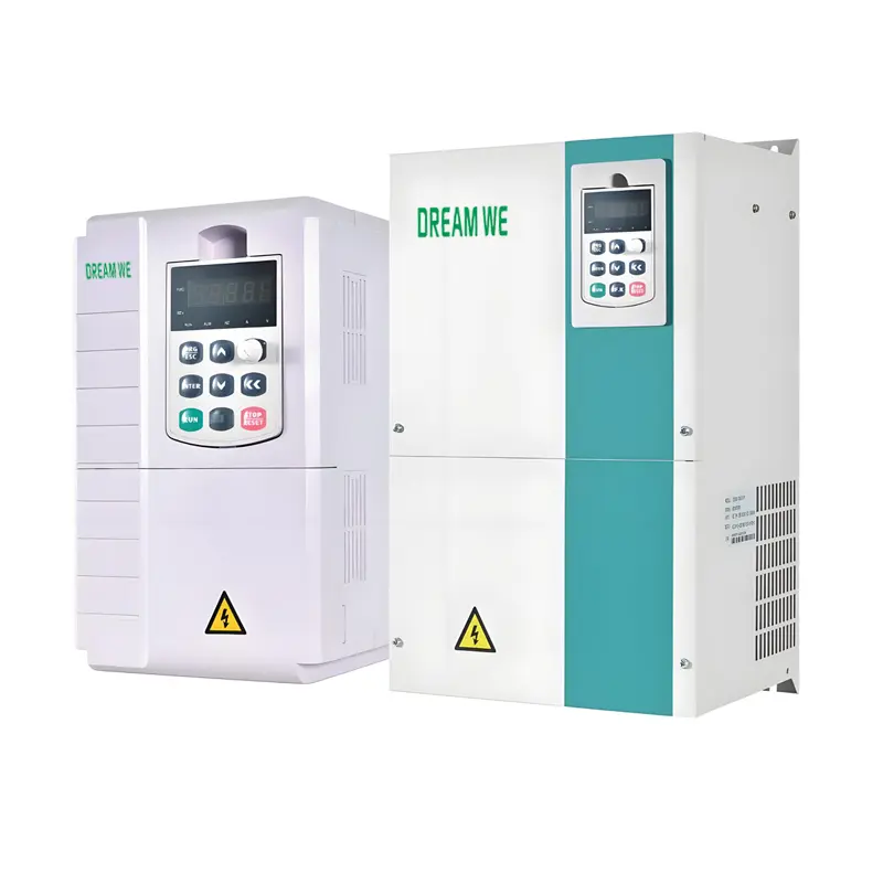
How to Choose the Right Frequency Inverter: A Comprehensive Guide & Brand Recommendations As a core device in industrial automation and motor speed control, selecting the right frequency inverter directly impacts production efficiency, energy consumption costs, and equipment stability. This guide covers key selection factors, load-matching principles, and functional requirements, while recommending suitable brands for various scenarios—with DREAM WE as our top recommendation. I. Key Factors for Selecting a Frequency Inverter To ensure compatibility, clarify these critical parameters before choosing a frequency inverter: 1. Basic Motor Specifications Rated Power: The inverter’s rated power should be ≥ the motor’s rated power. For special loads (e.g., heavy-duty or impact loads), increase the inverter power by 10-50%. Rated Voltage/Frequency: Must match the motor and grid specifications (e.g., AC 220V/380V, 50Hz/60Hz) to prevent damage. Rated Current: The inverter’s rated current should exceed the motor’s rated current, with a 10-20% margin for frequent start-stop scenarios. 2. Load Type Analysis Load characteristics determine the inverter’s required performance: Constant Torque Loads (e.g., conveyors, mixers): Require inverters with stable torque output, ideally vector control models. Variable Torque Loads (e.g., fans, pumps): Load torque correlates with the square of speed. Choose V/F control models for optimal energy savings. Impact Loads (e.g., crushers): Need inverters with strong overload capacity (typically 150% overload for 30+ seconds); upsizing by one power class is recommended. 3. Control Method Options V/F Control: Cost-effective and simple, suitable for low-precision applications like fans or pumps. Vector Control: Open-loop (no speed feedback) or closed-loop (with encoder) options offer high precision (0.1% accuracy), ideal for machine tools or cranes. Direct Torque Control (DTC): Fast response makes it suitable for high-dynamic scenarios like lifting equipment. 4. Environmental & Functional Needs Environmental Conditions: Temperature: Derate by 10% for every 10℃ above 40℃; use cooling systems if needed. Humidity: Avoid environments with >90% humidity (no...
Details
09/02/2025
Frequency Converters vs. Traditional Speed Regulation: Why Are Frequency Converters Called “Energy-Saving Powerhouses”? In industrial production and equipment operation, speed regulation is a common requirement—yet choosing between frequency converters and traditional methods (such as valve throttling, gear shifting, or voltage regulation) leads to drastically different energy efficiency outcomes. Frequency converters have earned the title of “energy-saving powerhouses” due to fundamental differences in their speed regulation principles and real-world performance. Here’s a detailed comparison: 1. Core Principle: “Adjusting Speed by Frequency” vs. “Wasting Energy to Regulate Speed” Traditional speed regulation: Energy waste is inherent in the principle Traditional methods do not change the motor’s rated speed; instead, they restrict output through external resistance. For example: Valve throttling (fans/pumps): To reduce airflow or water flow, valves or dampers are partially closed, creating artificial resistance. The motor still runs at full speed, but most energy is wasted as heat from throttling. Gear shifting (machines): Fixed gear ratios limit speed options, and energy is lost through mechanical friction during gear changes. Voltage regulation (small motors): Reducing voltage lowers speed but increases current, leading to higher copper losses in the motor (P=I²R), resulting in energy waste and overheating. Frequency converters: Energy input matches actual demand Frequency converters adjust the motor’s synchronous speed by changing the power supply frequency (via the formula n=60f(1-s)/p). When lower speed is needed, the frequency decreases, and the motor’s input power drops significantly (for fans and pumps, power is proportional to the cube of speed). This “on-demand energy supply” eliminates unnecessary energy consumption, as the motor only uses power matching the load. 2. Energy Efficiency Data: 30%-60% Savings in Typical Scenarios Practical cases show dramatic energy savings with frequency converters: Fans and pumps (the most energy-saving scenario): These are “variable torque loads,” where power consumption is proportional to the cube...
Details