
11/10/2025
How to Fix Corrupted Inverter Parameters: Complete Troubleshooting Guide If your inverter parameters have become corrupted or disrupted, this comprehensive guide will help you diagnose and resolve the issue efficiently. Common Causes of Parameter Corruption 1. Power-related Issues Voltage fluctuations or surges: Electrical instability can disrupt parameter storage Improper shutdown procedures: Powering off without proper shutdown sequence Battery backup failure: On units with memory backup batteries 2. User Error Accidental parameter changes: Unintentional modification of critical settings Incorrect programming: Entering wrong values during setup Unauthorized access: Lack of parameter modification controls 3. Hardware Problems Memory chip failure: Issues with the non-volatile memory storage Mainboard malfunction: Circuitry problems affecting parameter retention Connection issues: Loose cables disrupting communication 4. Environmental Factors Electromagnetic interference: From nearby high-power equipment Extreme temperatures: Operating outside recommended temperature range Humidity or moisture: Affecting internal components Step-by-Step Parameter Recovery Process 1. Initial Assessment Document current parameters: Record all visible settings before making changes Check for error codes: Note any displayed error messages Verify power supply: Ensure stable voltage input 2. Parameter Restoration Methods Method 1: Factory Reset 1. Access the parameter setting menu 2. Locate "Factory Reset" or "Parameter Initialization" function 3. Confirm the reset operation (this will erase all custom settings) 4. Restart the inverter and reconfigure as needed Method 2: Manual Parameter Reconfiguration Consult the manufacturer’s manual for default parameter values Re-enter motor specifications (voltage, current, frequency ratings) Configure control modes and operating parameters Set up protection functions and limits Method 3: Backup Restoration Upload previously saved parameter file if available Use manufacturer-provided software for parameter restoration Verify all critical parameters after restoration 3. Verification and Testing Perform no-load test run to check basic functionality Gradually apply load and monitor performance Verify all protection functions are working correctly Document final parameter settings for future reference Preventive...
Details
11/10/2025
How to Fix Inverter Display Flickering: Troubleshooting Guide If you’re experiencing display flickering on your inverter, you’re not alone. This common issue can be caused by several factors, but most can be resolved with some basic troubleshooting. Common Causes of Inverter Display Flickering 1. Power Supply Problems Unstable voltage input: Verify that the input voltage matches the inverter’s specifications Loose power connections: Check all power cables for secure connections Damaged power filter: Test and replace if necessary 2. Connection Issues Loose display cable: Ensure the cable connecting the display to the main board is properly seated Corroded connectors: Clean all connectors with appropriate contact cleaner Electromagnetic interference: Move the inverter away from motors, transformers, or other high-power devices 3. Hardware Failures Faulty display panel: Test with a replacement display if available Defective driver circuit: Inspect for damaged components on the driver board Main board issues: Contact a professional technician for diagnosis and repair 4. Configuration Problems Incorrect display settings: Reset to factory default settings Contrast or brightness issues: Adjust display parameters for optimal visibility Step-by-Step Troubleshooting Process Check power supply with a multimeter to ensure stable voltage Inspect all connections for tightness and corrosion Eliminate external interference by moving the inverter to a different location Reset display settings to factory defaults Test with replacement components if possible (display, cables) Contact professional repair service if the issue persists Preventive Maintenance Tips Regularly inspect and clean all connections Keep the inverter in a clean, dry environment Avoid overloading the inverter beyond its rated capacity Schedule periodic professional maintenance checks By following these troubleshooting steps, you can often resolve display flickering issues without extensive repairs. If you need further assistance, please provide your inverter’s make, model, and any error codes displayed.
Details
11/07/2025
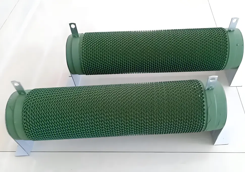
VFD Braking Unit Selection Guide: Complete Technical Reference Introduction Variable Frequency Drives (VFDs) are essential components in modern industrial automation, providing precise control of motor speed and torque. However, when dealing with high-inertia loads or frequent braking requirements, proper selection of braking units and resistors becomes critical to ensure system reliability and performance. I. When to Use a Braking Unit Before selecting a braking unit for your VFD system, it’s important to determine if one is actually needed. The following scenarios typically require braking units: High-Inertia Loads Applications such as centrifuges, large fans, and water pumps generate significant regenerative energy during deceleration that must be dissipated. Frequent Start-Stop Operations Equipment like cranes, elevators, and conveyors that require frequent starting, stopping, or reversing benefit from proper braking systems. Rapid Deceleration Requirements When process requirements specify deceleration times less than 1/3 of the natural stopping time, braking units become necessary. Gravity-Loaded Applications Vertical movement systems such as lifts and cranes continuously generate regenerative energy when lowering loads. Situations Where Braking Units May Not Be Needed: Low-inertia loads (small fans, pumps) Applications with infrequent braking requirements Systems with adequate natural deceleration time Small-power VFDs with sufficient built-in braking capacity II. Calculation Methods for Braking Unit Selection 1. Braking Power Calculation General Formula: P = (J × Δω²) / (2 × t) × η Where: J = Moment of inertia (kg·m²) Δω = Angular velocity change (rad/s) t = Deceleration time (s) η = Mechanical efficiency Special Formula for Lifting Equipment: PE = G × V × 9.81 PW = PE × (1 - n) Where: PE = Power from descending potential energy G = Weight of load (kg) V = Descending speed (m/s) PW = Braking power required n = Internal loss coefficient (typically 20%) 2. Braking Resistor Calculations Resistance Calculation: R =...
Details
11/04/2025
How to Handle Variable Frequency Drive (VFD) Failure: A Comprehensive Troubleshooting Guide Introduction Variable Frequency Drive (VFD) failure can be a costly and dangerous issue in industrial settings. When a VFD malfunctions or “fails catastrophically,” it can lead to unplanned downtime, equipment damage, and potential safety hazards. This comprehensive guide outlines the immediate steps to take when facing a VFD failure, how to diagnose the root cause, and preventive measures to avoid future issues. Immediate Safety Response Power Isolation Cut power supply: Immediately shut off the main power supply to the VFD Confirm de-energization: Verify that all power indicators are off before proceeding Lockout/tagout: Use lockout/tagout procedures to prevent accidental re-energization Hazard Assessment Evaluate environment: Check for smoke, fire, or hazardous fumes Use protective equipment: Wear appropriate PPE including gloves, safety glasses, and protective clothing Ventilate area: Ensure proper ventilation if smoke or fumes are present Fire safety: Have fire extinguishing equipment nearby if needed Area Securing Post warning signs: Place warning signs around the affected area Restrict access: Prevent unauthorized personnel from approaching the faulty equipment Notify personnel: Inform supervisors, maintenance teams, and safety officers Post-Failure Assessment Visual Inspection External examination: Look for signs of physical damage, burns, or deformation Check for blown fuses or tripped circuit breakers Inspect cable connections for damage or overheating Internal inspection (only after complete cooling): Look for capacitor swelling or explosion Check for burnt components or PCB damage Inspect cooling fans and heatsinks for blockages Documentation Photographic evidence: Take detailed photos of the failure from multiple angles Event timeline: Document the sequence of events leading to failure Data collection: Gather any available fault codes or diagnostic information Environmental factors: Note environmental conditions (temperature, humidity, etc.) Root Cause Analysis Electrical System Checks Power quality testing: Check for voltage fluctuations, harmonics, or transients Grounding verification: Verify...
Details
11/04/2025
How to Measure Variable Frequency Drive (VFD) Output Frequency: A Comprehensive Guide Introduction Variable Frequency Drives (VFDs) are essential components in modern industrial motor control systems. Accurate measurement of a VFD’s output frequency is critical for system commissioning, performance optimization, and troubleshooting. This guide explores various methods for measuring VFD output frequency, their advantages and limitations, and important considerations for accurate results. 1. Using a Digital Frequency Meter Digital frequency meters provide a direct and precise measurement method: Contact Measurement Method Connect the frequency meter probes to the VFD output terminals (usually labeled U, V, W) Ensure proper insulation and safety precautions Read the frequency directly from the digital display Non-Contact Measurement Method Use a clamp-on frequency meter around one of the VFD output cables This method eliminates the need for direct electrical connection Ideal for quick checks and troubleshooting Advantages: High accuracy, easy to use, real-time measurement Considerations: Select a meter compatible with PWM waveforms 2. Oscilloscope Measurement Technique Oscilloscopes offer both frequency measurement and waveform analysis: Connect the oscilloscope probe to the VFD output terminals Set appropriate voltage and time divisions on the oscilloscope Use the built-in frequency measurement function or manually calculate using the waveform period Observe waveform distortion and harmonic content Advantages: Provides visual waveform analysis, identifies harmonic issues Applications: Particularly useful during system commissioning and troubleshooting 3. PLC and Control System Integration Modern control systems can monitor VFD frequency through communication: Establish communication between PLC and VFD using protocols like Modbus, Profinet, or Ethernet/IP Configure appropriate register addresses for frequency data Display real-time frequency on HMI panels or monitoring software Implement data logging for historical analysis Advantages: Remote monitoring, automated data collection, integration with control logic Implementation: Requires proper communication configuration and programming 4. Motor Speed Calculation Method When direct VFD measurement isn’t possible, calculate...
Details
11/03/2025
How to Prevent and Fix Inverter Overheating in Summer: Complete Guide High temperatures in summer are one of the main causes of inverter failures. Studies have shown that for every 10°C increase in ambient temperature, the service life of an inverter is halved while the failure rate rises sharply. This comprehensive guide will detail the causes, solutions, and preventive measures for inverter overheating to help you keep your equipment running smoothly during hot weather. I. Understanding Inverter Overheating Causes 1. Excessive Ambient Temperature Impact Mechanism: Electronic components inside the inverter generate significant heat during operation, especially IGBT modules which produce more heat at high frequencies Temperature Threshold: Standard operating temperature range is -10°C to 40°C; derating is required above 40°C Accelerated Aging: High temperatures accelerate insulation material aging, reduce semiconductor device performance, and shorten capacitor lifespan 2. Poor Ventilation and Heat Dissipation Air Duct Blockage: Foreign objects like dust and cotton lint block heat sinks and air ducts Improper Installation: Insufficient surrounding space and inadequate heat dissipation distance Cabinet Design: Unreasonable control cabinet ventilation design that fails to effectively exhaust hot air 3. Cooling System Failure Fan Issues: Fan jamming, damage, or power cord detachment Fan Lifespan: Typical fan lifespan in industrial environments is 20,000-30,000 hours, which shortens in high-temperature environments Heat Sink Problems: Heat sink dust accumulation or thermistor damage 4. Overloading Issues Overload Operation: Actual load exceeds the inverter’s rated capacity Excessive Current: Excessive current generates significant heat, triggering overheat protection Improper Sizing: “Oversized load for undersized inverter” situation, where the inverter is not properly matched to the load requirements 5. Other Contributing Factors Power Grid Harmonics: Harmonic interference due to lack of reactor installation Parameter Settings: Excessively high carrier frequency increases power losses Component Aging: Performance degradation due to aging components like capacitors and semiconductors II. Emergency...
Details
11/03/2025
How to Properly Set Inverter Acceleration and Deceleration Times: A Comprehensive Guide If you’re working with industrial inverters, understanding how to set acceleration and deceleration times correctly is crucial for equipment performance, safety, and longevity. This expert guide will walk you through the entire process, from basic concepts to advanced optimization techniques. Understanding Acceleration and Deceleration Times Acceleration time refers to the duration required for the inverter output frequency to increase from 0Hz to the maximum operating frequency (typically 50Hz or 60Hz). Deceleration time is the time needed for the frequency to decrease from maximum back to 0Hz. These parameters control how smoothly your motor transitions between speed changes, directly impacting: Mechanical stress on equipment Energy consumption Production efficiency System reliability Consequences of Improper Settings Too Short Acceleration Time Excessive inrush current that may trigger overcurrent protection Increased mechanical stress on motor and transmission components Higher energy consumption during startup Potential equipment damage from shock loads Reduced component lifespan due to frequent stress Too Short Deceleration Time Regenerative energy overload causing DC bus overvoltage Unstable stopping or excessive coasting distance Increased mechanical vibration and noise Need for additional braking components Risk of damage to sensitive equipment Proper Setting Principles Setting Based on Load Characteristics Load Type Recommended Acceleration Time Recommended Deceleration Time Typical Applications Key Considerations Light Load 5-15 seconds 10-20 seconds Fans, pumps, air compressors Avoid insufficient starting torque Medium Load 10-30 seconds 15-35 seconds Conveyors, mixers, small machines Prevent material slippage Heavy Load 20-60+ seconds 25-50+ seconds Cranes, machine tools, extruders Minimize mechanical shock Setting Based on Motor Power Requirements Motor Power Range Suggested Acceleration Time Suggested Deceleration Time Small (<5.5kW) 5-15 seconds 8-20 seconds Medium (5.5-37kW) 10-30 seconds 15-35 seconds Large (>37kW) 20-60 seconds 25-50 seconds Step-by-Step Commissioning Process Phase 1: Initial Setup and Preparation Safety First...
Details
11/03/2025
Inverter SC Fault Code Troubleshooting Guide: How to Fix Short Circuit Issues If your inverter is displaying an SC fault code, it means the device has detected a short circuit condition. This comprehensive guide will help you diagnose and resolve SC faults in industrial inverters, ensuring safe and effective troubleshooting. Understanding Inverter SC Fault Codes SC stands for Short Circuit, indicating that the inverter has detected an abnormal current flow caused by a short circuit. Different manufacturers may use variations: SC1: Output short circuit (hardware detection) SC2: Impedance short circuit (software detection) SC3: Ground fault or earth leakage These fault codes are critical safety mechanisms designed to protect the inverter and connected equipment from damage. Common Causes of Inverter SC Faults Electrical Connection Issues Motor winding short circuits or ground faults Damaged output cables with insulation failure Loose or shorted terminals in the wiring system Contaminated electrical connections causing arcing Inverter Internal Failures IGBT module damage (most common cause) Current transformer malfunction Control board failures Driver circuit issues Power supply problems Operational and Environmental Factors Overloaded motor or seized mechanical components Insufficient cooling due to fan failure or blocked vents Incorrect parameter settings (acceleration time too short) Environmental contamination (dust, moisture, chemicals) Step-by-Step Troubleshooting Process Safety First Precautions Immediately stop operation and disconnect power Wait 15-20 minutes for capacitors to discharge completely Wear proper PPE: insulated gloves, safety glasses, and protective clothing Use insulated tools rated for electrical work Verify no voltage with a multimeter before starting inspection Initial Visual Inspection Check for obvious issues: Burn marks or discoloration on wiring or components Damaged insulation on cables Loose or corroded connections Physical damage to the inverter cabinet Signs of moisture or contamination Electrical Testing Procedures 1. Motor and Cable Testing Using a multimeter and megohmmeter: Test Steps: 1. Disconnect motor...
Details

10/31/2025
How to Fix Frequency Inverter Overload Fault (OL): A Comprehensive Guide If your frequency inverter is displaying an overload fault (OL), it indicates that the device has detected output current exceeding the rated value. This built-in protection mechanism activates to prevent potential equipment damage and ensure safe operation. Quick Troubleshooting Steps Emergency Shutdown: Immediately press the stop button to cut off the inverter output Load Inspection: Disconnect the motor load and check for any signs of jamming or excessive resistance Motor Check: Manually rotate the motor shaft to verify smooth operation Common Causes and Solutions 1. Excessive Mechanical Load Symptoms: Unusual motor noise, reduced operating speed, or sudden stoppage Effective Solutions: Thoroughly inspect the mechanical transmission system for obstructions or jams Verify that the load does not exceed the motor’s rated capacity Check and maintain proper lubrication of all moving parts Consider upgrading to a higher torque motor if overload occurs regularly 2. Incorrect Motor Parameter Configuration Symptoms: OL fault appears immediately upon startup or during operation Step-by-Step Solutions: Review and correct motor parameters in the inverter settings Input accurate values from the motor nameplate (current, power, voltage) Perform motor parameter auto-tuning function if available Consult the manufacturer’s manual for recommended parameter settings 3. Inadequate Acceleration/Deceleration Time Symptoms: OL fault occurs specifically during startup or stopping phases Optimization Solutions: Increase acceleration time settings to reduce startup current Implement S-curve acceleration for smoother torque transition Adjust deceleration time to prevent regenerative braking overload Consider adding a braking resistor for high-inertia loads 4. Insufficient Inverter Capacity Symptoms: OL fault occurs during normal operation, especially under load Capacity Solutions: Verify that inverter capacity matches or exceeds motor requirements Calculate required capacity based on load type (constant torque vs. variable torque) Consider oversizing for heavy-duty applications or frequent starts/stops Check for environmental factors (temperature,...
Details
10/30/2025
VFD Ground Fault (GF) Troubleshooting Guide: How to Diagnose and Fix Ground Faults in Variable Frequency Drives What is a VFD Ground Fault and Why Does it Happen? When your Variable Frequency Drive (VFD) shows a “GF” or “GFF” error code, it’s indicating a Ground Fault detection. This critical safety mechanism activates when the drive senses an abnormal current flow from the motor circuit to ground. Understanding what causes ground faults and how to fix them is essential for maintaining safe and reliable operation of your VFD system. Top Causes of VFD Ground Fault Alarms 1. Grounding System Problems High ground resistance: Resistance exceeding 4Ω (industry standard requirement) Loose ground connections: Poorly connected or corroded ground wires Damaged grounding cables: Physical damage reducing effectiveness Inadequate grounding electrodes: Improperly installed or corroded grounding rods Shared grounding systems: VFD ground shared with other equipment causing interference 2. Motor Issues That Cause Ground Faults Winding insulation failure: Short between windings and motor frame Aged motor insulation: Degraded from heat, moisture, or normal wear Bearing failure: Allowing windings to contact motor frame Voltage surge damage: Insulation breakdown from electrical transients Overheated windings: Thermal damage from overload conditions 3. Cable and Wiring Problems Damaged cable insulation: Physical injury from installation or operation Aged wiring: Insulation deterioration over time Incorrect installation: Excessive bending or pulling causing cracks Rodent damage: Chewed cables creating ground paths Excessive cable length: Capacitive currents triggering false alarms 4. VFD Internal Component Failures Hall sensor malfunction: Current detection sensor drift or failure IGBT module damage: Power semiconductor leakage to ground PCB circuit issues: Track damage or component failure Current transformer problems: Faulty current sensing components Capacitor failure: Internal short circuits in power capacitors 5. Environmental Factors High humidity: Moisture causing insulation breakdown Corrosive environments: Chemicals damaging components Dust accumulation: Conductive dust creating...
Details
10/30/2025
VFD Overheat Protection (OH) Troubleshooting Guide: How to Fix and Prevent What Does VFD OH Alarm Mean? When your Variable Frequency Drive (VFD) displays an “OH” or “OH1/OH2” error code, it indicates an Overheat Protection fault. This critical safety feature activates when internal temperatures exceed safe operating limits, automatically shutting down the drive to prevent component damage. Common Causes of VFD Overheating Issues 1. Environmental Factors High ambient temperature: Operating above recommended range (-5°C to +40°C) Inadequate ventilation: Poor air circulation in installation area Direct sunlight exposure: Equipment placed in unshaded locations Proximity to heat sources: Nearby machinery generating excessive heat 2. Cooling System Failures Malfunctioning cooling fan: Fan not working or running at reduced speed Clogged air pathways: Heat sinks blocked by dust, debris, or fibers Dirty heat exchangers: Accumulated dirt reducing thermal transfer efficiency 3. Electrical Load Problems Continuous overload conditions: Drive operating beyond rated capacity Oversized motor for drive: “Small drive, big motor” mismatch Motor defects: Short circuits, ground faults, or bearing failures causing high current 4. Internal Component Issues Faulty temperature sensors: Damaged thermistors or thermocouples IGBT module overheating: Power semiconductor failures Aging capacitors: Deteriorated components increasing heat generation 5. Programming Errors Excessively high carrier frequency: Increasing switching losses Incorrect thermal settings: Protection thresholds set too low Improper V/F curve configuration: Causing motor inefficiency and heating Step-by-Step Troubleshooting Procedure Immediate Response Actions Emergency shutdown: Stop VFD operation immediately upon OH alarm detection Power isolation: Turn off main power supply to ensure safety Cooling period: Allow equipment to cool naturally for 30-60 minutes Documentation: Record operating parameters at failure (frequency, current, voltage) Environmental Assessment Temperature verification: Measure ambient temperature to ensure it’s within -5°C to +40°C Ventilation evaluation: Check for adequate air flow around the equipment Heat source identification: Locate and isolate nearby heat-generating equipment Sunlight protection:...
Details
10/30/2025
Frequency Inverter Under Voltage Protection (LU) Troubleshooting Guide Meta Description: Comprehensive guide to diagnose and fix frequency inverter under voltage protection (LU) faults. Learn common causes, step-by-step troubleshooting, and preventive maintenance tips. Understanding LU Faults What is an LU Fault? LU Fault Definition: When a frequency inverter displays the “LU” fault code, it indicates an Under Voltage Protection event. This means the inverter has detected that either the input power voltage or the internal DC bus voltage has dropped below the factory-set or user-configured protection threshold. Key Characteristics of LU Faults Startup Issues: Inverter fails to start normally or trips immediately after power-on Operational Interruptions: Sudden shutdown during normal operation Visual Indications: Display panel shows “LU” or similar under voltage warning Audible Alarms: May be accompanied by warning beeps or indicator light flashes Protection Mechanism Explained The under voltage protection system activates when the DC bus voltage falls below 70% to 80% of the rated voltage. This protective measure: Blocks inverter pulse output to prevent damage to power components Shuts down the drive in a controlled manner Logs the fault for diagnostic purposes Prevents catastrophic failures of expensive components Common Causes of Under Voltage Protection 1. Power Supply Issues Grid Voltage Problems Chronic Low Voltage: Grid voltage consistently below 10% of rated value Transient Voltage Dips: Temporary voltage drops due to load changes Three-Phase Imbalance: Voltage differences between phases exceeding 5% Phase Loss: Complete or partial loss of one phase in three-phase systems Wiring and Connection Problems Loose Terminals: Input terminal screws not properly tightened Oxidized Connections: Corrosion at terminal points causing increased resistance Undersized Cables: Cable cross-sectional area insufficient for current requirements Damaged Conductors: Insulation breakdown or physical damage to power cables Switchgear Failures Contactor Issues: Pitted or worn contacts causing voltage drops Circuit Breaker Problems: Tripped breakers or...
Details