
10/29/2025
Frequency Inverter Overvoltage Trip (OV Fault) Troubleshooting Guide Overvoltage trip (OV fault) is one of the most common faults in frequency inverters, triggered when the DC bus voltage exceeds the safety threshold (typically 800V). Below is a comprehensive troubleshooting guide to help you resolve this issue effectively. Fault Cause Analysis Common Causes: Excessively short deceleration time (typically < 3 seconds) Motor operates in generating mode, energy cannot be consumed in time Excess energy causes DC bus voltage to rise Grid voltage fluctuations Input voltage exceeds ±15% of rated value Voltage surge caused by external factors such as lightning strikes Regenerative braking energy Frequent braking generates large amounts of regenerative energy Brake resistor aging or improper selection Incorrect parameter settings Overvoltage protection threshold set too low Inappropriate deceleration time parameter configuration Step-by-Step Troubleshooting Process Step 1: Emergency Response Immediate shutdown: Stop the equipment immediately and disconnect power supply Fault documentation: Record the exact fault code and operating conditions Voltage verification: Check if grid voltage is within normal range Step 2: Systematic Diagnosis Power Supply Assessment ① Measure grid input voltage (normal range: 380V±15%) ② Check power supply stability and identify any fluctuations ③ Verify if simultaneous starting/stopping of other equipment causes interference Parameter Configuration Check Deceleration time: Extend to appropriate range (10-30 seconds) Overvoltage protection: Adjust threshold to reasonable levels Braking parameters: Verify brake resistor configuration settings Hardware Inspection Brake resistor: Check for signs of aging, damage, or overheating Capacitor bank: Inspect DC bus capacitors for bulging or leakage Connection terminals: Ensure all electrical connections are tight and secure Step 3: Resolution Strategies For Excessive Deceleration Issues: Extend deceleration time parameters appropriately Enable “deceleration overvoltage stall prevention” function Implement S-curve deceleration profile for smoother operation For Grid-related Problems: Install voltage stabilizer or line reactor Implement surge protection devices Adjust overvoltage protection thresholds...
Details
10/29/2025
Frequency Inverter Overcurrent Trip (OC Fault) Troubleshooting Guide Overcurrent trip (OC fault) is the most common type of frequency inverter failure, typically accounting for over 40% of all inverter faults. Below is a comprehensive troubleshooting guide to help you resolve this issue effectively. Fault Cause Analysis Common Causes: Instantaneous overload: Sudden increase in motor load due to mechanical jamming or transmission mechanism failure Inadequate acceleration time: Excessively short acceleration periods generate damaging inrush currents Output short circuit: Damaged cable insulation or incorrect wiring connections Motor malfunction: Short-circuited windings or damaged bearings in the motor Incorrect parameter configuration: Improperly set protection parameters Step-by-Step Troubleshooting Process Step 1: Emergency Response Immediate shutdown: Stop the equipment immediately and disconnect power supply Safety waiting period: Allow 5 minutes for capacitors to discharge completely Fault documentation: Record the exact fault code and operating conditions Visual inspection: Check for burning odors, smoke, or unusual noises Step 2: Systematic Diagnosis Load Inspection Protocol 1. Disconnect motor load and perform no-load test on inverter 2. If no-load operation is normal, the issue is load-related 3. Inspect mechanical transmission system for jamming or resistance 4. Measure motor winding insulation resistance (minimum 5MΩ required) Electrical System Check Cable assessment: Thoroughly inspect output cables for insulation damage Connection verification: Ensure all terminal connections are tight and secure Current measurement: Use a clamp ammeter to monitor actual operating currents Insulation testing: Verify proper insulation resistance levels Parameter Configuration Review Acceleration settings: Adjust to appropriate levels (10-15 seconds for heavy equipment) Overload protection: Configure correct protection curves and thresholds Motor parameters: Validate accurate motor nameplate data entry Step 3: Resolution Strategies For Overload Conditions: Reduce mechanical load or upgrade to higher capacity inverter Implement S-curve acceleration/deceleration profiles Extend acceleration time settings appropriately Verify proper ventilation and cooling For Short Circuit Issues: Replace damaged...
Details
10/29/2025
Inverter Capacity Selection Guide: When to Upgrade Your VFD Size Introduction Proper inverter capacity selection is crucial for the reliable and efficient operation of variable frequency drive (VFD) systems in industrial automation. Choosing the right size ensures optimal performance, extends equipment lifespan, and prevents costly downtime. This comprehensive guide will help you understand when to increase inverter capacity, how to calculate the correct size, and avoid common pitfalls in the selection process. Key Insight: Inverter capacity should be selected based on motor current requirements rather than just power rating, as this ensures the drive can handle the actual electrical demands of the application. Theoretical Basis for Inverter Capacity Selection Basic Calculation Formulas Inverter Rated Current Selection I_inv ≥ K × I_motor Where: I_inv: Inverter rated current (A) I_motor: Motor rated current (A) K: Safety factor (1.1-1.5 depending on load characteristics) Inverter Rated Power Selection P_inv ≥ K × P_motor × (η_motor × cosφ_motor) / (η_inv × cosφ_inv) Where: P_inv: Inverter rated power (kW) P_motor: Motor rated power (kW) η: Efficiency coefficient cosφ: Power factor Key Parameters for Capacity Selection Parameter Description Impact on Capacity Selection Motor Rated Current Rated current value on motor nameplate Directly determines the minimum current rating of the inverter Starting Current Multiple Ratio of maximum starting current to rated current Affects the required overload capacity of the inverter Load Moment of Inertia J = GD²/4g (kg·m²) Loads with large inertia require larger capacity inverters Acceleration Time Time from 0 to rated speed Short acceleration time requires larger capacity Scenarios Requiring Increased Inverter Capacity Classification by Load Type Constant Torque Loads (Capacity Increase Required) Typical Applications: Conveyors, mixers, extruders, elevators Characteristics: T ∝ P/n = constant Capacity Factor: K = 1.2-1.5 Reason: Constant torque across the entire speed range, high current at low speeds Square Law Torque Loads (Capacity Can Be Appropriately Reduced) Typical...
Details
10/28/2025
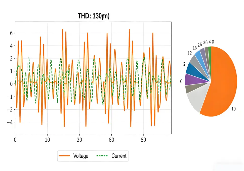
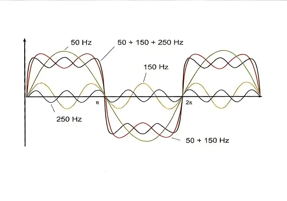
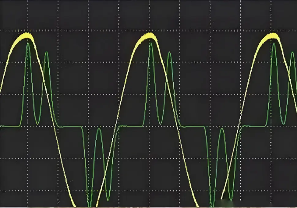
In-depth Comparative Analysis of Inverter Drive vs. Mains Frequency Motor Drive 1. Technical Principles and Voltage Characteristics: Core Root of Essential Differences 1.1 Voltage Waveform and Harmonic Characteristics (Core Distinction) Mains Frequency Drive: The power supply is a standard sine wave (50Hz/60Hz) that contains only fundamental frequency components. The waveform is continuous and smooth, with a low voltage rise rate (dv/dt, typically <100V/μs), and there are no harmonic pollution issues. The motor windings withstand gentle voltage changes, and the insulation system bears uniform stress. Inverter Drive: The output is a Pulse Width Modulation (PWM) pulse wave. It inverts DC voltage into a “quasi-sine wave” through high-frequency switching (carrier frequency: 2kHz-15kHz), which is essentially a superposition of numerous high-frequency square waves. Its core issues include: Abundant High-Order Harmonics: It contains (2u+1)-order harmonics (where u = modulation ratio), dominated by high-order harmonics at multiples of the carrier frequency. This increases the motor’s stator copper loss and rotor copper (aluminum) loss by 30%-50%. Voltage Spike Impact: When the cable impedance does not match the motor impedance, pulse wave reflection and superposition form voltage spikes. The peak value can reach 3 times the input voltage (e.g., over 1100V for a 380V input), causing high-frequency impact on the inter-turn insulation of windings. Electromagnetic Compatibility (EMC): Harmonics interfere with the power grid and surrounding electronic equipment through conduction and radiation, so additional input filters and reactors are required to suppress interference. 1.2 Speed Regulation Mechanism: From “Fixed Speed” to “Stepless Speed Adjustment” Mains Frequency Drive: Speed is determined by the motor’s pole pair number (formula: n=60f/p, where f = power frequency and p = pole pair number). Stepped speed regulation can only be achieved by changing the pole pair number (e.g., converting 4 poles to 6 poles), with a coarse speed adjustment step (typically ≥30% speed...
Details
10/28/2025
Detailed Compatibility Selection Table for Frequency Converters & Leakage Protectors Application Scenario Frequency Converter Specification Recommended Leakage Protector Parameters Installation & Wiring Requirements Matching Accessories & Calculation Examples Key Notes Civil/Small Equipment (e.g., laboratory motors, household inverter air conditioners) – Power: ≤ 5.5kW – Carrier frequency: 2–8kHz – Typical model: INVT GD200A-2R2G-4 – Input current: 10A (for GD200A-2R2G-4) – Type: Type A (compliant with IEC 60755 standard) – Leakage Operating Current (IΔn): 30mA – Operating Time (tΔ): ≤ 0.1s – Rated Current (In): 1.2×10A = 12A (select 16A grade) – Brand recommendation: Siemens 5SU1 16A/30mA/A – Install on the input side (between the MCCB and converter input filter) – Maintain a spacing of ≥ 15cm between input and output cables; do not bundle them – Grounding resistance ≤ 10Ω (civil standard) – Use a 2.5mm² multi-strand copper ground wire – Accessories: Input EMC filter (small-capacity, ≤0.1μF) – Leakage calculation (for general products): IΔn ≥ 10×(Ig1+Ign+3×(Ig2+Igm)) Example: Ig1=0.11mA, Ign=0mA, Ig2=1.32mA, Igm=0.36mA → IΔn≥10×(0.11+0+3×1.68)=51.5mA (select a 30mA Type A anti-harmonic model) – Prioritize personal safety; AC-type protectors are forbidden (false tripping rate >80%) – Refer to the INVT GD200A series manual General Industrial Equipment (e.g., small pumps, fans) – Power: 5.5kW ~ 37kW – Carrier frequency: 5–10kHz – Typical model: Mitsubishi FR-D700-15K-CHT – Input current: 32A (for 15kW/380V) – Type: Type B (anti-harmonic/surge-resistant) – IΔn: 50–100mA – tΔ: ≤ 0.1s – In: 1.5×32A = 48A (select 63A grade) – Brand recommendation: Mitsubishi NV-C 63A/100mA/B – Route input and output cables through separate steel conduits with a spacing of ≥30cm – Grounding resistance ≤4Ω (industrial standard) – Ground wire cross-section: 4mm² (matches 63A rated current) – Keep the distance between the leakage protector and converter ≤5m – Accessories: Input EMC filter + DC reactor – Leakage calculation (for anti-harmonic products): IΔn ≥10×(Ig1+Ign+Igi+Ig2+Igm) Example: Ig1=0.15mA, Ign=0.5mA, Igi=1.2mA, Ig2=2.1mA,...
Details
10/27/2025
Can Frequency Converters Be Connected to Leakage Protectors? Comprehensive Guidelines 1. Core Compatibility Logic: Why Do Ordinary Leakage Protectors Fail? The high-frequency switching characteristics of frequency converters generate two types of special currents, which cause false tripping of traditional leakage protectors: Harmonic Leakage Current: The high-frequency switching (typically in the kHz range) of IGBT modules produces a large number of 3rd and 5th harmonics. These currents easily leak through the cable-to-ground capacitance. AC-type leakage protectors can only detect sinusoidal leakage currents and cannot identify harmonic components, which directly triggers false tripping. Stray Capacitive Current: There is distributed capacitance between the frequency converter’s output cables, the ground, and the motor housing. Under high-frequency voltages, capacitive currents (usually in the mA range) are generated; these superimpose on normal leakage currents and exceed the leakage protector’s operating threshold. Therefore, it is necessary to select types (Type A/Type B) that are compatible with non-sinusoidal leakage currents. Their key differences are as follows: Leakage Protector Type Applicable Scenarios Detectable Leakage Current Types Compatibility in Frequency Converter Scenarios Type AC Pure power-frequency equipment (e.g., ordinary motors, heaters) Sinusoidal AC leakage current Not recommended (false tripping rate > 80%) Type A Equipment with pulsating DC (e.g., frequency converters, rectifiers) Sinusoidal + pulsating DC leakage current Recommended for general scenarios (compatibility: 70%) Type B Equipment with high-frequency harmonics/smooth DC Sinusoidal + pulsating DC + high-frequency harmonic leakage current Recommended for complex industrial scenarios (compatibility: 95%) 2. Installation and Configuration: Details Determine Stability 1. In-depth Logic of Installation Location Installation on the Input Side (Grid Side): This is the preferred option, as it only detects leakage current on the grid side and avoids harmonic interference from the frequency converter. It is recommended to install the leakage protector between the main circuit breaker and the frequency converter’s input filter, forming...
Details
10/27/2025
When a frequency converter drives a motor, vibration issues typically stem from three core categories: parameter mismatch, wiring/hardware problems, and load/mechanical issues. It is a common operational abnormality in variable frequency speed regulation systems. 1. Mismatched Parameter Settings (Most Common Cause) Incorrect input of motor parameters (e.g., rated voltage, frequency, pole count, stator resistance) that do not match the actual motor specifications, leading to deviations in the frequency converter’s control algorithm. In vector control mode, inadequate or incomplete motor self-learning fails to accurately identify the motor’s inherent characteristics, resulting in imprecise magnetic field orientation. An excessively low carrier frequency (typically recommended to be 2–10 kHz) causes high harmonic interference during low-frequency operation, triggering motor vibration. 2. Wiring and Hardware Issues Loose connections or poor contact on the frequency converter’s output side, or cables that are overly long or undersized, leading to three-phase voltage imbalance. Damaged IGBT modules, aging filter capacitors in the frequency converter, or inter-turn short circuits in the motor windings/bearing wear, which cause abnormal vibration during operation. Poor grounding allows harmonic interference to destabilize the motor’s magnetic field—an issue particularly noticeable during high-frequency speed regulation. 3. Load and Mechanical Transmission Issues Excessive misalignment between the motor and its load (e.g., pumps, fans, reducers) or loose/damaged couplings, resulting in mechanical impact-induced vibration. Load jamming, stalling, or frequent load fluctuations that the frequency converter cannot respond to in a timely manner, causing speed instability and vibration. Insufficiently secured motor bases, where the resonance frequency coincides with the operating frequency, amplifying vibration amplitude. 4. Operating Mode and Frequency Range Issues Motor operation in the low-frequency range (typically below 5 Hz) leads to insufficient torque and high harmonic content, easily causing “crawling vibration.” Failure to enable torque compensation or slip compensation functions results in unstable output torque during low-frequency operation, leading to...
Details
10/27/2025
Ten Major Advantages of Using Variable Frequency Speed Regulation This question is highly practical. Below are the ten core advantages of variable frequency speed regulation, covering key scenarios such as energy conservation, control, and operation and maintenance: 1. Significant Energy Savings and Lower Energy Costs When a motor operates at a non-rated speed, its energy consumption is proportional to the cube of the speed. Variable frequency speed regulation accurately matches load requirements, eliminating energy waste from the “big horse pulling a small cart” phenomenon. The energy-saving rate reaches 20%-50% in most applications. 2. Stepless Speed Regulation with High Control Precision It offers a wide speed regulation range (typically above 1:100) and enables continuous, smooth speed adjustment. It meets precise speed demands under different working conditions, far exceeding the adjustment accuracy of traditional methods like pole changing and voltage regulation. 3. Smooth Startup to Protect Motors and Equipment Adopting a soft-start method, the starting current can be controlled within 1.2 times the rated current. This avoids the large current impact during power frequency startup, reduces wear on motor windings and mechanical transmission components, and extends equipment service life. 4. Simplified Control Logic and Improved Automation It enables remote control and automatic speed adjustment via PLCs, touch screens, and other devices. It supports multi-speed operation and PID closed-loop control (e.g., pressure and flow closed-loop control), making it suitable for complex industrial automation scenarios. 5. Reduced Power Grid Impact During Startup The large current from power frequency startup causes grid voltage fluctuations, affecting other electrical equipment. Variable frequency soft start prevents this issue and ensures stable grid operation. 6. Enhanced Stability of Production Processes Precise speed control ensures consistent production parameters (such as flow, pressure, and tension). It minimizes product quality fluctuations, especially for high-process-demand scenarios like assembly lines, chemical production, and printing....
Details
10/24/2025
How to Detect VFD Harmonics?VFD Harmonic Detection Guide: Tools, Process & Standards for Industrial Users Detecting harmonics generated by Variable Frequency Drives (VFDs) is crucial for ensuring the stability of power grids and the safe operation of motor systems. This process involves selecting appropriate detection tools, formulating scientific testing plans, and analyzing data accurately. Below is a detailed, actionable detection guide tailored to B2B industrial scenarios (e.g., manufacturing plants, water treatment facilities) : I. Core Detection Tools & Equipment Selection Power Quality Analyzers (Primary Tool) Function: Professional instruments designed to measure voltage/current harmonics, THD (Total Harmonic Distortion), harmonic orders (up to 50th or 100th), and other key parameters. Recommended Models: Fluke 438-II, Yokogawa WT1800E, Chauvin Arnoux CA8335 (suitable for industrial environments with high anti-interference requirements). Application Tips: Choose analyzers with VFD-specific measurement modes to filter out carrier frequency interference and ensure data accuracy. Current/Voltage Sensors Current Sensors: Use clamp-on current transformers (CTs) or Rogowski coils (for large currents) to avoid breaking the circuit. Ensure the sensor’s frequency range covers 50/60Hz (fundamental) to at least 2kHz (high-order harmonics). Voltage Sensors: Employ voltage dividers or differential probes to measure line voltage, ensuring compatibility with the VFD’s output voltage range (e.g., 380V, 480V). Auxiliary Tools Data loggers: Record harmonic variations over long periods (e.g., 24 hours) to identify peak load harmonic characteristics. Oscilloscopes: Observe the waveform distortion of voltage/current to visually confirm harmonic presence (suitable for on-site troubleshooting). II. Step-by-Step Detection Process Pre-Detection Preparation Define Detection Objectives: Clarify whether to measure grid-side harmonics (VFD input terminal) or motor-side harmonics (VFD output terminal), and determine key parameters (THD, individual harmonic order content). Safety Check: Ensure the VFD is in normal operation, and wear insulated protective equipment (gloves, goggles) to avoid electric shock. Sensor Installation: Connect current sensors to the VFD’s input/output three-phase lines. Connect...
Details
10/24/2025
Harmonic Effects on VFD Motors: Causes, Impacts & Suppression Solutions Harmonics are voltage/current components in the power grid with frequencies that are integer multiples of the fundamental frequency. Generated by nonlinear loads such as Variable Frequency Drives (VFDs), they exert multi-dimensional negative effects on the operational performance, service life, and efficiency of motors (especially induction motors), as detailed below: I. Deterioration of Core Performance and Efficiency Significant Increase in Copper Loss and Iron Loss Copper Loss (Winding Loss): Harmonic currents generate additional Joule heat, and the loss is proportional to the square of the current frequency (Formula: \(P_{cu} \propto f^2\)). High-frequency harmonics cause a sharp rise in winding temperature. Iron Loss (Core Loss): Divided into eddy current loss and hysteresis loss. Eddy current loss is proportional to the square of the frequency, while hysteresis loss is approximately proportional to the frequency. Harmonics accelerate the alternating frequency of the core magnetic field, intensifying core heating and reducing the motor’s energy conversion efficiency. Practical Impact: When the motor’s input power remains constant, its output power decreases, and efficiency may drop by 5%-20% (depending on harmonic content), leading to increased operational costs. Torque Ripple and Unstable Speed The interaction between harmonic magnetic fields and the fundamental magnetic field generates “negative sequence torque” and “pulsating torque”: Negative sequence torque hinders motor rotation and reduces effective output torque; pulsating torque causes periodic speed fluctuations, resulting in vibration and noise, which impairs the precise control of motors (e.g., speed regulation in production lines, stable flow control of pumps). II. Increased Mechanical Wear and Shortened Service Life Aggravated Vibration and Noise If the harmonic frequency is close to the motor’s mechanical resonance frequency, resonance will occur, leading to a sudden increase in vibration amplitude. Long-term operation may cause mechanical failures such as bearing wear, rotor eccentricity, and frame...
Details
10/24/2025
Core Hazards of VFD Harmonics and Impact Scenarios In the process of converting alternating current (AC) to direct current (DC) and then inverting it back to adjustable-frequency AC, variable frequency drives (VFDs) generate non-sinusoidal harmonic currents and voltages. These harmonics pose multi-dimensional hazards to power systems, equipment, and production operations—especially in industrial B2B scenarios, where they may lead to severe economic losses and safety risks. Below is a detailed breakdown of specific hazards: I. Hazards to Power Systems Increased Grid Losses and Reduced Power Supply Efficiency Harmonic currents induce additional active power losses (including increased copper loss and iron loss) in power transmission lines, transformers, and other electrical equipment, which lowers grid transmission efficiency. Power companies must invest more to offset these losses, costs that may ultimately be passed on to enterprise users through electricity pricing. For regions with underdeveloped power grid infrastructure—such as Africa, Southeast Asia, and South America—this loss issue is more pronounced and can even worsen power shortages. Compromised Grid Voltage Quality and Voltage Distortion Harmonic voltages superimpose on fundamental voltages, causing voltage waveform distortion, fluctuations, and flicker. This undermines the stability of the entire power grid and may trigger malfunctions in sensitive equipment (e.g., precision instruments, PLC control systems), particularly impacting manufacturing production lines that rely on stable power supply. Interference with Relay Protection and Automatic Control Devices Harmonics can distort the operational logic of relay protection devices, fuses, and other equipment, leading to false tripping or failure to activate. In severe cases, this can escalate power grid faults and cause large-scale blackouts. For example, in factory power distribution systems, harmonics may trigger conflicts between VFDs and the protection devices of other equipment, disrupting production continuity. Malfunctions in Reactive Power Compensation Equipment Harmonic currents cause overcurrent and overheating in capacitor compensation devices, accelerating capacitor aging or...
Details
10/23/2025
Beyond Distance: What Other Factors Affect VFD and Motor Performance? In industrial drive systems, the performance of Variable Frequency Drives (VFDs) and motors is not only influenced by the cable distance between them but also by a combination of equipment parameters, environmental conditions, operational settings, and maintenance quality. These factors directly impact the system’s stability, energy efficiency, and service life—especially in complex industrial scenarios across target markets like Africa, Southeast Asia, and South America. Below is a detailed analysis of key influencing factors and their impacts: I. Equipment Parameter Matching 1. VFD and Motor Rating Compatibility Core Impact: Mismatched ratings between VFDs and motors are a primary cause of performance issues. For example, using a VFD with a lower power rating than the motor will lead to insufficient output torque, frequent overcurrent protection triggers, and even damage to the VFD’s power modules. Conversely, an oversized VFD may result in low-load operational inefficiency, increased harmonic distortion, and higher energy consumption. Key Requirements: Ensure the VFD’s rated current, voltage, and power match the motor’s specifications. For special scenarios (e.g., heavy starting loads in South American mines), select a VFD with a rated current 1.1–1.2 times higher than the motor’s. 2. Motor Type Adaptability Core Impact: Different motor types have varying compatibility with VFDs. Standard induction motors may experience increased iron loss and noise when operated at variable frequencies, while dedicated inverter-duty motors are designed with low-loss cores and reinforced insulation to handle high-frequency harmonics. Practical Suggestion: For long-term variable-speed operation, recommend inverter-duty motors to customers in target markets. If using standard motors, limit the frequency range (e.g., 5–50Hz) and reduce the carrier frequency appropriately. 3. Cable Quality and Specifications Core Impact: Beyond distance, cable quality and specifications significantly affect performance. Using aluminum-core cables instead of copper-core ones increases resistance and voltage drop,...
Details