
10/23/2025
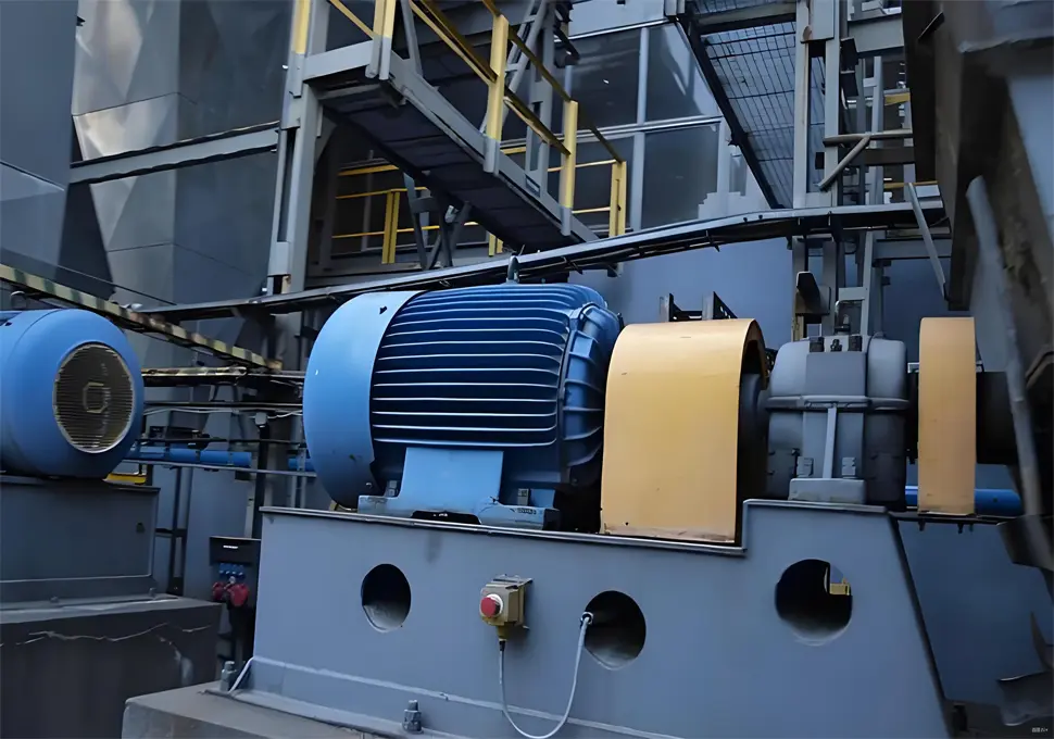
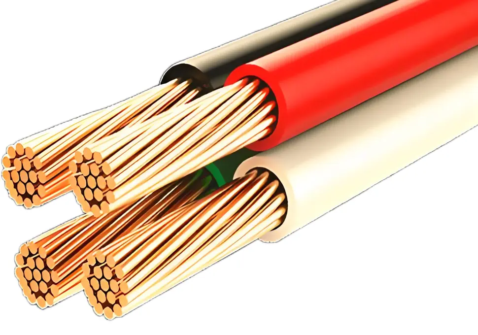
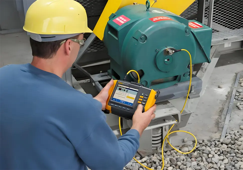
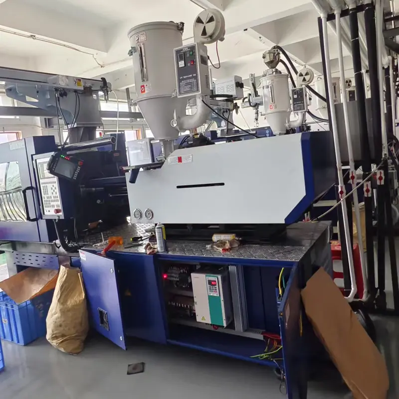
How to Determine the Distance Between a VFD and a Motor Cable? The distance between a Variable Frequency Drive (VFD) and a motor cable is not “calculated” through complex formulas, but rather a “reasonable laying distance” comprehensively determined based on factors such as equipment installation scenarios, electrical performance limitations, and engineering specification requirements. The core logic is to define the maximum allowable cable length or select suitable cables and auxiliary equipment according to actual installation needs, while ensuring the motor operates normally and avoiding performance losses and equipment failures. Below are the specific determination methods and key considerations: I. Core Determination Basis: Electrical Performance Limitations (Critical Conditions to Avoid Failures) 1. Voltage Drop Limitation (Most Basic Consideration) Cable transmission will cause voltage drop. If it exceeds 5% of the motor’s rated voltage, it will lead to insufficient motor torque and severe heating. The maximum allowable cable length can be estimated using the voltage drop formula: Voltage Drop Calculation Formula (Three-Phase Circuit): \(\Delta U = \frac{\sqrt{3} \times I \times L \times R_0}{1000}\) Parameter Explanations: \(\Delta U\): Maximum allowable voltage drop (V), usually 3%-5% of the motor’s rated voltage (e.g., for a 380V motor, the allowable voltage drop ranges from 11.4V to 19V); I: Motor rated current (A); L: Cable length (m); \(R_0\): Cable resistance per unit length (Ω/km), which can be found in cable specification tables (e.g., \(R_0≈17.5Ω/km\) for 1mm² copper core cables, and \(R_0≈4.4Ω/km\) for 4mm² copper core cables). Derived Formula for Maximum Allowable Cable Length: \(L = \frac{\Delta U \times 1000}{\sqrt{3} \times I \times R_0}\) Example: For a 380V motor with a rated current of 10A, using a 4mm² copper core cable (\(R_0=4.4Ω/km\)) and an allowable voltage drop of 5% (19V): \(L = \frac{19 \times 1000}{1.732 \times 10 \times 4.4} ≈ 248m\) That is, the cable length in this scenario is recommended not to...
Details
10/23/2025
What Are the Impacts of an Excessively Long Distance Between a VFD and a Motor Cable? An excessively long distance between a Variable Frequency Drive (VFD) and a motor cable can trigger a series of electrical performance issues, which may lead to equipment failure or shortened service life in severe cases. Especially in industrial B2B scenarios, such problems will directly affect production stability. The following is a detailed analysis of the specific impacts and core causes: I. Core Negative Impacts and Technical Principles 1. Output Voltage Distortion and Reduced Motor Efficiency Principle: Cables have distributed capacitance and inductance. During long-distance transmission, the PWM (Pulse Width Modulation) waveform output by the VFD will undergo reflection and distortion due to the cable’s parasitic parameters, resulting in an increase in the peak voltage at the motor terminal (i.e., a “voltage spike”) that exceeds the motor’s rated voltage tolerance range. Consequences: Increased iron loss and copper loss in the motor, severe heating, reduced actual output power, and higher energy consumption. For example, cables over 100 meters long may cause the voltage distortion rate to exceed 5% and motor efficiency to drop by 3%-10%. 2. Sharp Increase in the Risk of Motor Insulation Damage Principle: The peak value of voltage spikes can reach 2-3 times the VFD’s DC bus voltage (e.g., the peak voltage of a 380V VFD can exceed 1500V). Long-term exposure to such spikes will break down the insulation layer of the motor windings. Consequences: Motor faults such as inter-turn short circuits and ground leakage, and even direct motor burnout in severe cases. In the high-temperature and high-humidity environments of target markets like Africa and Southeast Asia, the insulation aging rate will accelerate further. 3. Aggravated Electromagnetic Interference (EMI) Principle: A long cable acts like an “antenna.” The high-frequency harmonics output by the...
Details

10/22/2025
I. Core Basis for Inverter Brake Resistor Selection The core function of an inverter brake resistor is to dissipate the regenerative energy of a motor. When the motor is in a deceleration, braking, or heavy-load lowering state (e.g., elevator descent, machine tool emergency stop), it acts as a generator and feeds energy back to the inverter’s DC bus. If this energy is not dissipated promptly, the bus voltage will rise excessively and trigger protection mechanisms. Selection should focus on “how to safely and efficiently dissipate regenerative energy,” with three core criteria: regenerative power, braking time, and allowable temperature rise. II. Key Parameters to Confirm Before Selection (Prerequisites) Before selecting a brake resistor, the following four types of basic parameters must be obtained, as they directly determine the resistor’s specifications: Rated Parameters of the Inverter and Motor Motor rated power \( P_{e} \) (kW, e.g., 5.5kW); Motor rated voltage \( U_{e} \) (V, e.g., 380V); Motor rated current \( I_{e} \) (A, can be estimated using \( P_{e} = \sqrt{3}U_{e}I_{e}\cos\varphi \), where \( \cos\varphi \) is 0.8~0.9); Inverter rated capacity \( S_{e} \) (kVA, usually matching the motor power—e.g., a 5.5kW motor typically requires an inverter with a capacity of approximately 7.5kVA). System Braking Requirements Braking type: Short-term braking (e.g., a single emergency stop of a machine tool) or continuous braking (e.g., frequent elevator up/down movements, crane load lowering); Braking time \( t_{b} \) (seconds, the time to decelerate from rated speed to a stop, e.g., 2s); Braking frequency: The number of braking cycles per unit time (e.g., 20 times per hour). Parameters of the Inverter’s Built-in Brake Unit If the inverter has a built-in brake unit (standard for most medium-to-high power inverters), check the manual to obtain the brake unit’s maximum allowable braking current \( I_{bmax} \) (A, e.g., 20A)...
Details
10/22/2025
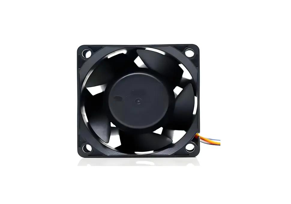
Why Is the Inverter Fan Not Working? Causes and Impacts on the Inverter I. Common Causes of an Inverter Fan Not Working The inverter fan is a core heat dissipation component, and its failure to rotate is usually related to power supply issues, hardware faults, control logic errors, or the external environment. Specific causes can be categorized as follows: 1. Power Supply and Circuit Failures (Basic Troubleshooting Items) Broken fan power supply circuit: The fan is generally powered by the inverter’s internal auxiliary power supply (e.g., DC12V/24V). If the fuse in the power supply circuit blows, the terminal is loose, or the wire is broken, the fan will have no power input and stop rotating. For example, the fan power supply circuit of some inverters is in series with a small fuse, which may blow due to overload after long-term use. Faulty auxiliary power module: If the inverter’s internal auxiliary power supply (which powers the fan and control circuit) is damaged (e.g., capacitor bulging, chip burnout), it will directly cut off the fan’s power supply. This issue may also be accompanied by phenomena such as no display on the panel and abnormal control signals. 2. Fan Hardware Damage (High-Frequency Fault Points) Burnt fan motor: When the fan operates continuously for a long time, its motor windings may short-circuit or open due to insulation aging and bearing wear. Judgment method: After powering off the inverter, use a multimeter to measure the resistance of the fan motor windings. If the resistance is infinite (indicating an open circuit) or close to 0Ω (indicating a short circuit), the motor is damaged. Jammed fan bearings: Lack of oil in the fan bearings, excessive dust accumulation, or long-term wear will cause the rotor to jam and fail to rotate. Symptoms include significant resistance when manually rotating...
Details
10/22/2025
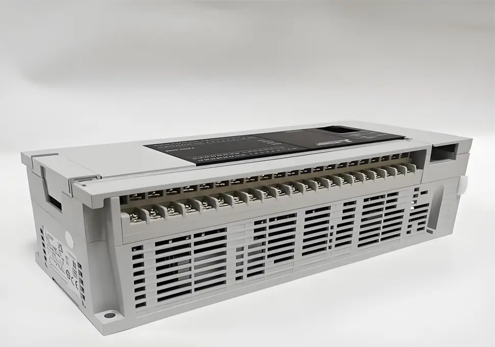
How to Control a Frequency Inverter with a PLC? A Complete Guide Controlling a frequency inverter (VFD) with a PLC is a prevalent application in industrial automation. It primarily enables the control of motor speed, start/stop operations, and other key parameters through electrical connections and program logic. Below is a detailed breakdown of the implementation methods and step-by-step procedures: I. Control Principle As the core control component, the PLC (Programmable Logic Controller) sends commands to the frequency inverter via digital or analog signals. In response, the inverter adjusts its output voltage and frequency to regulate the motor’s operating status—including start/stop functionality, speed adjustments, and forward/reverse rotation. II. Common Control Methods Based on the type of signals used, the main control methods are categorized as follows: 1. Digital Control (Switch Control) Application Scenario: Ideal for scenarios that only require motor start/stop and forward/reverse control, without the need for real-time speed adjustments (or when speeds are preset via the inverter panel). Connection Method: Connect the PLC’s Digital Output (DO) terminals to the inverter’s control terminals (e.g., “Forward Start”, “Reverse Start”, “Stop” terminals). Example: Link the PLC’s DO points to the inverter’s “FWD” (Forward), “REV” (Reverse), and “STOP” terminals. The inverter is activated when the PLC outputs high/low levels or triggers relay contacts. Advantages: Features simple wiring and strong anti-interference capabilities. 2. Analog Control Application Scenario: Perfect for applications that demand continuous motor speed adjustments (e.g., real-time speed modifications based on process requirements). Connection Method: Connect the PLC’s Analog Output (AO) terminals to the inverter’s Analog Input (AI) terminals. Most inverters support 0~10V voltage signals or 4~20mA current signals. The inverter outputs different frequencies in direct correspondence to the magnitude of the analog signal (e.g., a 0~10V signal corresponds to a 0~50Hz frequency output). Notes: Analog signals are prone to interference. Use shielded...
Details
10/21/2025
VFD Parameters to Check During Motor No-Load Operation During the motor no-load operation phase, checking the parameters of a Variable Frequency Drive (VFD) is a core step to verify equipment compatibility and operational stability. Focus should be placed on three key categories: output electrical parameters, protection function parameters, and control mode & frequency parameters, as detailed below: I. Output Electrical Parameters (Real-Time Monitoring Category) These parameters require real-time observation throughout no-load operation to ensure no abnormal fluctuations or threshold violations. They are critical for evaluating the VFD’s output performance: Output Three-Phase Current Core Requirement: The three-phase current must be balanced (unbalance degree ≤10%, calculated as: (Maximum current – Minimum current)/Average current × 100%), and the no-load current must align with the motor’s specifications (typically 20%~50% of the motor’s rated current). Key Check Points: No significant current fluctuations during operation (fluctuation range ≤5% of the motor’s rated current) and no instantaneous peak current (to prevent triggering overcurrent protection). Output Three-Phase Voltage Core Requirement: The three-phase voltage must be symmetrical (voltage difference ≤5% of the VFD’s rated output voltage), and the voltage waveform should closely resemble a sine wave (no severe distortion or abnormal harmonics; an oscilloscope can be used for auxiliary detection). Key Check Points: In V/F control mode, voltage must change proportionally to the output frequency (e.g., 50Hz corresponds to the rated voltage, while 10Hz corresponds to 20% of the rated voltage), with no sudden voltage spikes or drops. DC Bus Voltage Core Requirement: During stable operation, the DC bus voltage fluctuation range must be ≤±5% of the rated value (e.g., for a VFD with 380V input, the DC bus voltage typically ranges from 510V to 540V, and fluctuations must be controlled within 25V). Key Check Points: No threshold-exceeding voltage surges in the bus during start-stop phases (e.g., no voltage...
Details

10/21/2025
VFD Motor No-Load Operation: Acceptance Standards & Checklist The acceptance of VFD (variable frequency drive)-driven motor no-load operation is a critical verification step before equipment commissioning. It requires multi-dimensional index testing to confirm that the equipment operation status meets design requirements and safety standards. The specific acceptance criteria are divided into the following four categories: I. Electrical Performance Acceptance Criteria 1. Current Parameter Acceptance Three-phase current balance: The unbalance degree of the VFD’s output three-phase current shall be ≤10% (calculation formula: (Maximum current - Minimum current)/Average current × 100%), with no significant fluctuation (fluctuation range ≤5% of rated current). No-load current value: It shall comply with the motor technical manual, usually 20%~50% of the motor’s rated current (reference range for asynchronous motors; synchronous motors shall be adjusted according to specific models), without abnormal high or low values. No overcurrent alarm: During the entire operation process (including start-up, stable operation, and shutdown phases), the VFD shall have no “overcurrent” or “overload” alarms, and the current monitoring value shall not exceed 80% of the VFD’s overcurrent protection setting. 2. Voltage Parameter Acceptance Three-phase voltage symmetry: The difference between the VFD’s output three-phase voltages shall be ≤5% of the rated output voltage, with no obvious phase shift (the voltage waveform can be detected by an oscilloscope, which shall be close to a sine wave without severe distortion). DC bus voltage: The fluctuation range of the DC bus voltage during stable operation shall be ≤±5% of the rated value (e.g., for a VFD with 380V input, the DC bus voltage is usually 510~540V, and the fluctuation shall be controlled within 25V). No overvoltage/undervoltage alarm: When the input power voltage fluctuates within ±10% of the rated value, the VFD shall have no “overvoltage” or “undervoltage” alarms, and the output voltage shall change normally with frequency (voltage...
Details
10/21/2025
Inverter Motor No-Load Operation: Technical Requirements & Best Practices Guide No-load operation of inverter-driven motors is a critical phase in the commissioning process. Its core objective is to verify the compatibility between the motor and inverter, the stability of equipment operation, and the rationality of parameter settings. The technical requirements cover multiple aspects including preliminary preparations, parameter configuration, operational procedures, condition monitoring, and safety compliance, which are detailed as follows: I. Technical Requirements for Preliminary Preparations 1. Equipment and Wiring Inspection The motor must comply with the voltage and frequency range of the inverter’s output. Its nameplate parameters (rated voltage, rated frequency, rated speed, etc.) should be clearly marked and compatible with the inverter. The motor must also have good insulation performance—use a megohmmeter to test the insulation resistance between phases and to ground, which should be no less than 0.5MΩ for low-voltage motors. The inverter should be properly sized, with a rated output current not less than 1.1~1.2 times the motor’s rated current, and support the motor’s control mode (e.g., V/F control, vector control). Wiring must be secure and correct: the main circuit power wiring should be free of looseness and short circuits; the motor’s three-phase wiring should have the correct phase sequence and symmetry; the grounding line must meet standard specifications (grounding resistance should comply with equipment requirements). The control circuit wiring should be error-free to avoid signal interference. Remove obstacles around the motor, check the lubrication of motor bearings (fill with specified lubricating oil), ensure the fan is firmly installed, and confirm there is no mechanical jamming during rotation. 2. Environmental and Power Supply Conditions The operating environment’s temperature, humidity, and dust concentration must meet the rated working conditions of the inverter and motor (typically 0~40℃ for temperature, 20%~90% for humidity without condensation). The input power supply voltage...
Details
10/20/2025
Dust & Corrosive Gas Limits for Frequency Converters: Africa, Brazil, SE Asia Guidelines Combined with the typical environmental characteristics (e.g., high temperatures, high humidity, heavy dust, and corrosive gases in some areas) of countries and regions including Africa (including Ethiopia), Brazil, Pakistan, the Philippines, Thailand, and Egypt, the allowable concentrations of dust and corrosive gases in frequency converter installation environments are still based on equipment manufacturers’ technical specifications. However, protective requirements need to be adjusted according to local environmental challenges. Below are specific standards and practical suggestions tailored to these regions: I. Allowable Dust Concentration & Adaptation Solutions These regions commonly face issues like industrial dust (e.g., manufacturing zones in Egypt and Pakistan), wind-blown sand (e.g., areas near the Sahara in Africa and desert regions in Egypt), and agricultural dust (e.g., farmland surroundings in Thailand and the Philippines). Dust concentration control must be stricter, with targeted protective measures: 1. General Allowable Concentration Standards For both standard industrial-grade and sealed frequency converters, suspended dust concentration should ideally be ≤ 0.1 mg/m³ (cumulative weight concentration). This standard covers most basic industrial scenarios in these regions, preventing dust from quickly blocking heat dissipation channels. Conductive dust (e.g., metal particles in African mining areas) and adhesive dust (e.g., sugar dust in Brazilian sugar refineries) are strictly prohibited. Such dust easily adheres to circuit boards in high-humidity environments, causing short circuits, so their allowable concentration should be near 0. 2. Regional Targeted Requirements Wind-blown sand-prone areas (e.g., Egypt and northern African desert regions): Even with IP54+ rated frequency converters, additional dust covers and sand filters are necessary. Internal dust concentration here should be controlled to ≤ 0.05 mg/m³ to prevent fine sand from seeping into equipment gaps. Agricultural/light industrial zones (e.g., Thai rice mills, Philippine coconut processing plants): Dust is mostly organic and tends to clump when...
Details
10/15/2025
Core Advantages of VFD Motors: Ideal for Africa, Brazil, Pakistan & Southeast Asia (2025 Guide) 1. Extreme Energy Efficiency: Cut Electricity Costs by 20%-60% – Perfect for High-Energy-Cost Regions The biggest advantage of VFD (Variable Frequency Drive) motors is their ability to save energy by matching speed to load—a top priority for users in Africa, Brazil, and Pakistan, where electricity costs are often high or supply is unstable. Unlike fixed-speed motors, which run at full power even when demand is low, VFD motors use an inverter to adjust power frequency and voltage in real time. For example: In Nigerian factories, VFD-driven fans reduce energy use by 30% during off-peak production hours; In Philippine water treatment plants, VFD pumps cut monthly electricity bills by up to 40% compared to old fixed-speed models; In Brazilian agricultural irrigation systems, VFD motors adapt to changing water needs, saving farmers thousands of reals each year on energy costs. This energy efficiency also helps address frequent power shortages in countries like Ethiopia and Egypt, as VFD motors reduce overall grid demand. 2. Stable Performance for Unstable Grids: Soft Start & Voltage Adaptation Many target regions (e.g., Pakistan, parts of Africa) face unstable power grids with voltage fluctuations. VFD motors solve this issue with soft start technology and voltage adjustment capabilities: Soft start limits the starting current to 1.5-2 times the rated current (compared to 5-7 times for fixed-speed motors), preventing damage from sudden voltage spikes—this is critical in Kenya or Tanzania, where grid surges are common; Automatic voltage regulation keeps VFD motors running smoothly even if the grid voltage drops by 10%-15%, avoiding downtime for Thai textile factories or Egyptian food processing plants. This stability reduces repair costs, which is vital for small businesses in the Philippines or Ethiopia with limited maintenance budgets. 3. Durable Design for Tough...
Details
10/14/2025
1. Solid Configuration Lays the Foundation for Value The value of the DreamWe Inverter is carefully shaped by its robust technical configuration. At its core, it adopts a DSP control system that integrates three control modes: sensorless vector control (SVC), vector control with an encoder (VC), and V/F control. It can output a starting torque of 150% at a low frequency of 0.5Hz, with a speed control accuracy of ±0.1% and a speed adjustment range of 1:100—all of which allow it to accurately meet the needs of different loads. This performance is particularly crucial for scenarios such as fan operation, pump systems, and high-precision speed regulation, as it effectively prevents mechanical resonance and low-frequency oscillation, thereby reducing equipment wear. With a wide power range spanning 0.75kW to 1200kW, the DreamWe Inverter offers suitable options for industrial scenarios of all scales. Models with power ratings from 0.75kW to 15kW come equipped with a built-in braking unit, enabling quick stopping without the need for additional accessories. Furthermore, its rich I/O interface configuration—including 7 digital inputs, 1 high-speed pulse input, 2 analog inputs, and multiple output terminals—eliminates the need for extra investment in expansion modules, making system setup more flexible and efficient. 2. Scene Adaptability Reduces Comprehensive Investment In industrial applications, the ability of equipment to adapt to different scenes directly impacts the efficiency of actual investment—and the DreamWe Inverter stands out with significant advantages in this area. For common industrial scenarios like water drainage and ventilation, its built-in features (such as 16-segment simple PLC, multi-speed control, and PID control) enable automatic operations (e.g., water level adjustment and air volume adaptation) without the need to write complex control programs. The speed tracking and restart function allows for smooth, impact-free startup of rotating motors, preventing equipment damage and restart-related losses caused by sudden shutdowns....
Details
10/14/2025
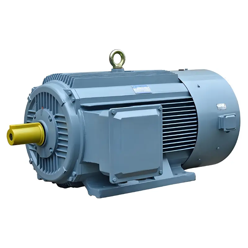
What Are the Application Scenarios of Inverter Motors? Inverter motors, with core advantages such as wide-range speed regulation, energy efficiency, and stable starting and braking, are applied across industrial, commercial, and residential sectors—especially in working conditions that require dynamic speed adjustment, energy conservation, or high operational stability. Below are specific categories and typical scenarios: I. Industrial Production (Core Application Scenario) Industry is the primary application field for inverter motors, as they significantly improve production efficiency, reduce energy consumption, and adapt to various precision or high-load equipment: Machining Equipment CNC machine tool spindles: Speed needs to be adjusted based on different materials (e.g., metal, plastic) and cutting processes (milling, drilling, grinding). Inverter motors enable precise speed regulation from 0 to several thousand r/min, ensuring machining accuracy. Textile machinery (carding machines, looms): Roller speed must be dynamically adjusted according to yarn thickness and fabric density to prevent yarn breakage or uneven fabric patterns. Printing machines: Adjusting roller speed to match ink drying speed ensures clear printed patterns, accurate color registration, and reduced waste rates. Fluid Control Equipment Industrial water pumps (e.g., factory circulating water pumps, water supply pumping stations): Flow is adjusted based on production water demand or pipeline pressure. Compared with fixed-frequency motors, inverter motors save 30%–50% of energy and avoid energy waste from “overcapacity operation.” High-pressure fans/blowers (e.g., chemical workshop ventilation, pneumatic conveying systems): Air volume is adjusted according to workshop exhaust gas concentration or material conveying volume, reducing noise and the risk of motor overload. Air compressors (factory compressed air supply): Displacement is adjusted via frequency conversion to match the real-time air demand of pneumatic equipment, avoiding energy loss and equipment wear caused by frequent starts and stops of fixed-frequency motors. Material Conveying and Lifting Equipment Inverter-driven conveyors (e.g., assembly lines, mine conveyors): “Soft starting” prevents material impact and...
Details