
10/13/2025
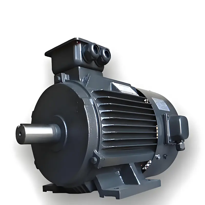
Differences Between Inverter Motors and Ordinary Motors The core differences between inverter motors and ordinary motors (usually referring to fixed-frequency asynchronous motors) lie in their design objectives, structural characteristics, and operating methods. The former is optimized specifically for scenarios requiring “adjustable speed,” while the latter is only suitable for constant-speed operation with a “fixed-frequency power supply.” Below is a comparison across 7 key dimensions, supplemented by applicable scenarios and selection recommendations to help you fully understand the differences between the two: I. Core Differences: Comparison Across 7 Dimensions Comparison Dimension Ordinary Motors (Fixed-Frequency Asynchronous Motors) Inverter Motors Design Objective Adapted to fixed-frequency power supplies (e.g., 50Hz in China, 60Hz in overseas markets) to achieve constant-speed operation, with a focus on “efficiency under rated working conditions.” Adapted to variable-frequency power supplies (ranging from 0 to several hundred Hz) to enable wide-range speed adjustment, with an emphasis on “stability and reliability across the entire speed range.” Motor Structure 1. Rotor: An ordinary cast-aluminum rotor with low conductor bar resistance (prioritizing efficiency at rated speed); 2. Heat Dissipation: Relies solely on natural heat dissipation through the housing or a simple fan (fixed speed, resulting in constant heat dissipation capacity); 3. Insulation: Uses conventional insulating materials, which only withstand rated voltage fluctuations of the power grid. 1. Rotor: A specially designed rotor (e.g., deep-slot rotor, copper conductor bars) with slightly higher conductor bar resistance (suppressing the “slip rate” at low speeds to reduce heat generation); 2. Heat Dissipation: Equipped with an independent forced cooling fan (powered by a separate power source, unaffected by motor speed, ensuring efficient heat dissipation even at low speeds); 3. Insulation: Adopts high-frequency and high-voltage resistant insulating materials (resisting “peak voltage” generated by variable-frequency power supplies to prevent insulation breakdown). Speed Control Speed is fixed (determined by power supply frequency: Speed ≈ 60 × Frequency...
Details
10/12/2025
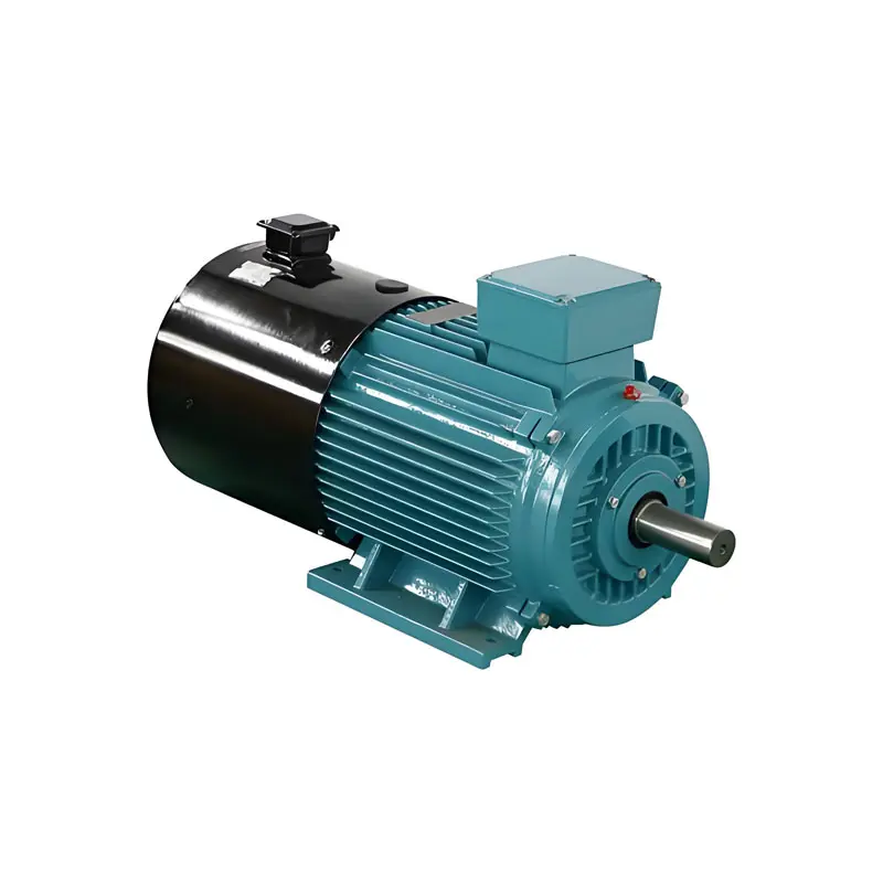
What Is a VFD Motor? A VFD motor—short for Variable Frequency Drive motor—is also known as a variable-frequency speed-regulating motor or a dedicated inverter motor. It is a type of electric motor specifically designed to work with a variable frequency drive (VFD) to achieve precise speed control. Below is a detailed overview: How Does a VFD Motor Work? A VFD motor operates in tandem with a frequency converter (the core component of a VFD system). First, the frequency converter receives the user’s set speed command. It then converts the fixed-frequency alternating current (AC) from the power grid into direct current (DC) and inverts this DC power back into AC power with adjustable frequency and voltage. This modified AC power is then supplied to the VFD motor. According to the formula \(n = 60 \times f / p\) (where n = motor speed, f = power supply frequency, and p = number of motor pole pairs), adjusting the frequency converter’s output frequency (f) directly changes the motor’s rotational speed (n). This enables stepless speed regulation—meaning the motor can smoothly adjust to any speed within its design range, rather than being limited to fixed speeds. Key Features of VFD Motors High Energy Efficiency: For applications where load torque is proportional to the square of the motor speed (e.g., fans, pumps), VFD motors deliver on-demand power. Unlike traditional systems that use throttle valves or dampers to control output (which wastes energy), VFD motors adjust speed to match the load. This typically results in 20% to 50% energy savings—and sometimes even more. Precise Speed Control & Smooth Start/Stop: VFD motors support stepless speed regulation across their set range. During startup, they limit inrush current to within the motor’s rated current, eliminating sudden torque spikes. Start and stop processes are smooth, reducing stress on both the power grid and mechanical equipment. This extends the overall lifespan...
Details
09/30/2025
Why Use a Variable Frequency Drive (VFD)? The core purpose of using a Variable Frequency Drive (VFD) is to achieve energy savings, optimize production processes, and reduce equipment wear by precisely controlling motor speed—addressing the pain points of traditional fixed-speed motors across three key dimensions: cost, efficiency, and equipment lifespan. 1. Significantly Save Energy and Reduce Operating Costs This is the most critical reason for using a VFD, especially for centrifugal loads such as fans, pumps, and compressors. Motor energy consumption is proportional to the cube of its speed (following the “affinity laws”). For example, if the motor speed is reduced to 75%, its energy consumption drops to only about 42% of that at full speed. It replaces the traditional load control method of “valve or damper throttling,” eliminating energy waste caused by forced flow restriction. 2. Achieve Precise Speed Regulation and Improve Production Quality VFDs enable stepless speed regulation from 0 to 100% of the rated speed, meeting the flexible speed requirements of different processes. They can stably control production parameters: for instance, adjusting pump speed to regulate water pressure or fan speed to control air volume, thus preventing product defects caused by parameter fluctuations. They support custom speed curves. For example, a production line can accelerate slowly during startup to avoid material impact, and decelerate gradually during shutdown to protect both equipment and materials. 3. Protect Equipment and Extend Service Life The “soft start/soft stop” function of VFDs is key to protecting motors and associated equipment. It avoids the current surge (6 to 8 times the rated current) that occurs during traditional direct startup, reducing wear on motor windings and bearings and lowering the risk of motor burnout. It reduces mechanical impact: for connected equipment like conveyors, gearboxes, and pipelines, this lowers the probability of component loosening or breakage,...
Details
09/30/2025
The Advantages of Variable Frequency Drives (VFDs) The core advantage of a Variable Frequency Drive (VFD) is its ability to enable precise speed control for AC motors while significantly reducing energy consumption. It addresses the inefficiency of traditional fixed-speed motor control methods, such as throttling or dampering. 1. Energy Savings (The Most Significant Advantage) It matches motor speed to actual load demand. For example, a fan or pump running at 75% speed consumes only about 42% of the energy it uses at full speed. This is based on the affinity laws for centrifugal loads. It eliminates energy waste from the common “constant speed operation + load adjustment via valves/dampers” setup in traditional systems. 2. Precise Process Control It allows stepless speed adjustment within a wide range, typically 0–100% of the rated speed. This ensures stable and accurate control of parameters like flow rate, pressure, or temperature in industrial processes. Compared to fixed-speed setups with rough load regulation, it reduces product defects and improves process consistency. 3. Extended Equipment Lifespan It enables soft starting and stopping of motors, which eliminates the high inrush current (up to 6–8 times the rated current) during direct-on-line (DOL) starting. This reduces mechanical shock to the motor, gearbox, and connected machinery. It minimizes wear on components like belts, bearings, and valves by avoiding sudden speed changes. 4. Reduced Maintenance Costs Lower mechanical stress from soft starts and stops reduces the frequency of part replacements, such as for bearings and couplings. It simplifies system design by replacing mechanical speed regulators (e.g., variable-speed pulleys) with electronic control. Electronic control has fewer moving parts and lower maintenance needs. 5. Enhanced System Protection & Safety It comes with built-in protection functions, including overcurrent, overvoltage, undervoltage, overload, and overheating protection for both the motor and the VFD itself. It prevents damage from abnormal operating conditions (e.g., motor...
Details
09/28/2025
How to Determine the Required Inverter Protection Level for a Specific Environment To determine the appropriate inverter protection level for a specific environment, the core principle is to first analyze the “threat factors” in the environment (such as dust, moisture, temperature, and corrosive gases) and then match the suitable protection level by referencing international standards (the IP rating system) and the special requirements of the inverter’s application scenario. The entire process can be completed in 4 steps, while common misunderstandings should be avoided to ensure accurate selection. Step 1: Understand the Core Protection Standard – The IP Rating System (Basic Framework) Currently, the globally recognized protection level standard for inverters is based on IEC 60529 (corresponding to China’s national standard GB/T 4942.1), commonly known as the “IP code”. It is structured as “IP + the first characteristic digit (dust protection level) + the second characteristic digit (water protection level)”. It is essential to first grasp the meaning of key levels, as this forms the foundation for subsequent matching. 1. First Characteristic Digit (Dust Protection Level: Grades 0–6; higher grades indicate stronger protection) Grade Description of Protection Capability Core Applicable Scenarios 0 No protection Only used in absolutely dust-free laboratory environments (rarely applied) 1 Protects against solids with a diameter of ≥ 50mm (e.g., large gravel, tools) Dry, dust-free indoor fixed locations (e.g., small equipment in offices) 2 Protects against solids with a diameter of ≥ 12.5mm (e.g., small gravel, fingers) Dry, low-dust indoor environments (e.g., control cabinets in workshops far from dust-generating points) 3 Protects against solids with a diameter of ≥ 2.5mm (e.g., metal chips, dust particles) Indoor environments with mild dust (e.g., non-cutting areas in mechanical processing workshops) 4 Protects against solids with a diameter of ≥ 1.0mm (e.g., fine dust, fibers) Indoor environments with moderate dust (e.g., areas around control...
Details
09/27/2025
Compliant Inverter Installation: Must-Follow Precautions for Electrical Safety Installing an inverter requires balancing electrical safety, equipment performance, and long-term stability. Strict attention must be paid to four core dimensions: environment selection, electrical connection, mechanical installation, and safety protection. Below are detailed precautions, sorted by operation process and importance: I. Preparations: Environment Selection and Inspection The operating environment of an inverter directly affects its service life and failure rate. Before installation, confirm that the environment meets the equipment’s requirements: Temperature Control The ambient temperature should be maintained between -10°C and 40°C (some industrial-grade inverters can operate in an extended range of -20°C to 50°C, subject to the product manual). Avoid direct sunlight or placement near heat sources (such as boilers, motors, and heaters). If the temperature exceeds 40°C, the inverter’s service life may decrease by approximately 10% for each 1°C increase. Additional cooling measures—such as cooling fans, air conditioners, or heat dissipation ducts—are necessary, especially for high-power inverters (11kW and above). Humidity and Dust Prevention The relative humidity should be controlled between 40% and 90% (no condensation). Avoid installing the inverter in humid environments (e.g., basements, areas near bathrooms) to prevent short circuits on the circuit board. In humid regions, dehumidifiers or anti-condensation heaters must be installed. Keep the inverter away from dust, oil mist, and corrosive gases (e.g., acid-base gases in chemical workshops). If the environment is dusty, select an inverter with a dust cover or install it in a closed control cabinet. The cabinet must have ventilation openings, and the filter screen should be cleaned regularly. Vibration and Space Requirements The vibration acceleration at the installation location should not exceed 5.9m/s² (0.6g). Avoid rigidly connecting the inverter directly to vibration sources (e.g., pumps, fans). If necessary, install vibration dampers (such as rubber vibration isolators). Sufficient heat dissipation space must be reserved around the inverter: ≥10cm...
Details
09/25/2025
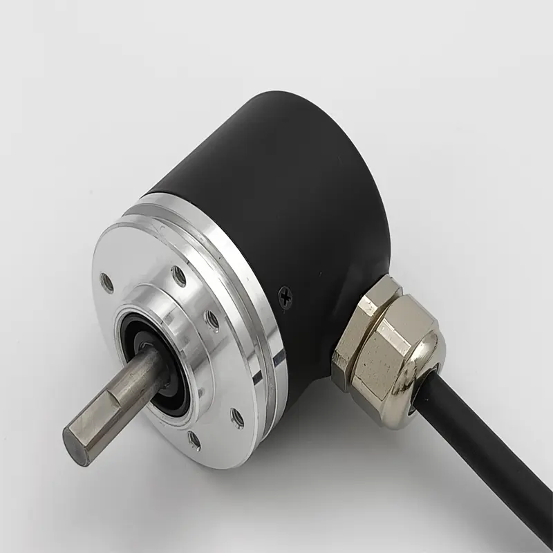
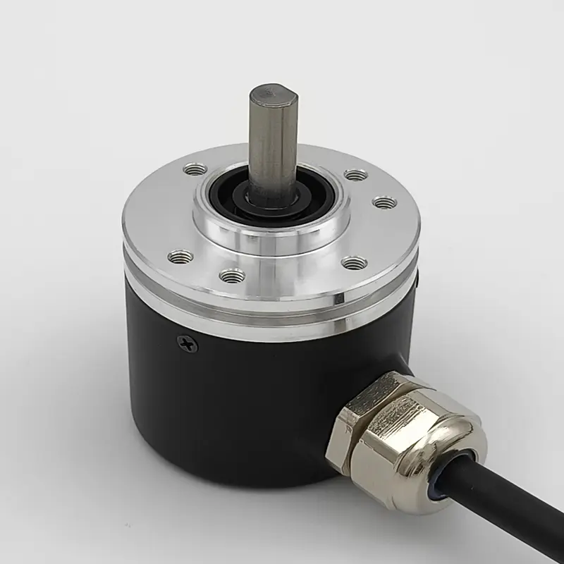
What Is an Encoder? (Linked to Closed-Loop Vector Control Scenario) In the context of closed-loop vector control (as discussed in the previous article on “zero-speed torque“), an encoder is a high-precision electromechanical sensor that converts the mechanical motion (rotation or linear displacement) of a motor’s rotor into electrical signals. These signals are then transmitted to the inverter or controller, providing real-time data on the motor’s position, speed, or direction—all of which are critical for achieving precise control such as zero-speed torque. Core Functions of an Encoder (Aligned with Closed-Loop Vector Control) Position Feedback: It captures the exact angular or linear position of the motor’s rotor. For example, in zero-speed torque scenarios, even when the motor is stationary (0 RPM), the encoder continuously outputs position signals (with precision up to 65,536 PPR, or Pulses Per Revolution). This allows the controller to know the rotor’s exact orientation, which is essential for adjusting the magnetic field and current to maintain stable torque. Speed Calculation: By measuring the frequency of position pulses over a fixed period of time, the encoder helps calculate the motor’s real-time speed (RPM). In closed-loop control, this speed data is compared with the target speed to adjust the inverter’s output, ensuring smooth speed regulation—including the transition to zero speed. Direction Detection: Advanced encoders (e.g., incremental encoders with A/B phase signals) can distinguish the rotor’s rotation direction (clockwise or counterclockwise). This is useful for applications like robot joints or lifting equipment, where directional accuracy prevents unintended movement during torque maintenance. Common Types of Encoders (As Mentioned in Zero-Speed Torque Control) 1. Incremental Encoders Working Principle: It outputs a series of pulses as the rotor rotates. To determine the absolute position (e.g., for zero-speed torque initialization), it requires a “homing process” (calibrating to a reference point) when the system starts up. Use...
Details
09/25/2025
How Closed-Loop Vector Control Achieves “Zero-Speed Torque” with an Encoder The core of how closed-loop vector control achieves “zero-speed torque” lies in using high-precision position and speed feedback from an encoder, which enables the inverter to precisely control the magnetic field and current even when the motor is stationary—thereby generating stable torque. Working Principle 1. The Key Role of the Encoder Provides real-time rotor position information (with precision ranging from 1024 to 65536 PPR) Calculates the number of pole pairs and electrical angle to enable field-oriented control Continuously outputs position signals even at 0 RPM (revolutions per minute) 2. Control Implementation Process Field-Oriented Control: Decomposes the motor current into excitation current components and torque current components, allowing independent regulation of magnetic field and torque. Zero-Speed Strategy: When the motor speed approaches zero, the control mode switches from the speed loop to the position loop to enhance position stability. A small position deviation is set as the source of the torque command to trigger torque output without causing motor rotation. The PI (Proportional-Integral) controller outputs current commands in real time, adjusting the torque current component to maintain stable torque. 3. Key Technical Parameters Encoder Type: Incremental encoders (require homing to determine absolute position) or absolute encoders (position is known immediately after power-on) Control Cycle: High-speed computation with a cycle of 100–200 µs (microseconds) Torque Response Time: Typically less than 10 ms (milliseconds) Low-Speed Performance: Capable of stable operation at speeds as low as 0.01 RPM Application Scenarios Tension control in printing machines and paper machines (maintains constant tension when materials are stationary) Hover function in lifting equipment (keeps loads stable without drifting when stopped) Static torque maintenance in robot joints (prevents joint sagging during positioning) Stationary clamping of machine tool spindles (secures workpieces tightly during machining) Common Issues and Solutions...
Details
09/24/2025
A VFD (Variable Frequency Drive) is an electronic device that controls the speed of an AC motor by adjusting the frequency and voltage of the power supplied to it. Instead of running a motor at full speed all the time, a VFD lets you: Adjust motor speed to match the task, which saves energy Start and stop smoothly (soft start/stop) to reduce mechanical stress Control torque for precise operation Reverse direction without extra switches It works by converting incoming AC power to DC, then inverting it back to AC at the desired frequency. This gives you fine control over motor performance. VFDs are used in pumps, fans, conveyors, compressors, and many industrial machines where variable speed and energy efficiency are important.
Details
09/23/2025
How Does a VFD Work? A Simple Guide to Variable Frequency Drives A VFD (Variable Frequency Drive) is an electronic controller that adjusts the speed of an alternating current (AC) motor by modifying the frequency of the electrical power supplied to it. This technology is widely used in industrial, commercial, and residential applications to optimize motor performance and reduce energy consumption. A Step-by-Step Breakdown of How a VFD Works VFDs operate through three core stages, plus additional control components, to regulate motor speed effectively: 1. Rectifier Stage The incoming AC power (from a standard electrical grid) is first converted into direct current (DC) using semiconductor devices like diodes or thyristors. This conversion process creates a “DC bus”—a temporary storage point for the converted electrical energy. 2. DC Bus Stage A set of capacitors in the DC bus smooths out fluctuations in the DC voltage. These capacitors act like a reservoir, ensuring a steady, consistent flow of DC power to the next stage of the VFD. 3. Inverter Stage Using fast-switching transistors (such as IGBTs—Insulated Gate Bipolar Transistors—or MOSFETs—Metal-Oxide-Semiconductor Field-Effect Transistors), the VFD converts the steady DC power back into AC power. Unlike the original grid power, this output AC has adjustable frequency and voltage—the key to controlling motor speed. 4. Motor Control Logic By varying the frequency of the AC power sent to the motor, the VFD directly changes the motor’s rotational speed (since motor speed is proportional to power frequency). To maintain optimal motor performance, the VFD also adjusts the voltage in tandem with the frequency—a method known as V/Hz (Voltage-to-Frequency) control. This keeps the motor’s magnetic field at the correct strength, preventing inefficiency or damage. 5. Control Circuitry A built-in microprocessor runs specialized algorithms to manage the VFD’s operation. It regulates critical parameters like speed and torque, and...
Details
09/22/2025
How Does Ambient Humidity Affect Inverter Operation? Ambient humidity significantly impacts inverter performance and lifespan. Understanding these effects is crucial for maintaining reliable operation. Key Effects of Humidity on Inverters 1. Reduced Insulation Performance High humidity lowers electrical insulation strength Risk of leakage, creepage, or insulation breakdown increases Long-term exposure above 90% relative humidity is particularly harmful 2. Metal Component Corrosion Humid environments accelerate oxidation of metal contacts Increased contact resistance leads to abnormal heating Severe cases can cause solder joint failure or wire breakage 3. Electronic Component Degradation Capacitors, resistors, and semiconductors experience parameter drift when exposed to moisture Electrochemical migration may occur on chip pins Component aging accelerates, shortening overall lifespan 4. Impaired Heat Dissipation Moisture causes dust and debris to adhere more easily to heat sinks This buildup forms an insulating layer reducing cooling efficiency May trigger frequent overheating protection events The Dangers of Condensation When temperature changes cause water vapor to condense: Liquid water can create direct short circuits Control circuits may malfunction unpredictably Risk is especially high when power is applied to a wet inverter Recommended Humidity Control Measures Ideal range: 40%-60% relative humidity Acceptable range: 20%-80% (without condensation) Install dehumidification equipment and heaters when necessary Maintain proper ventilation to prevent moisture accumulation Conduct regular inspections and address moisture issues promptly
Details
09/22/2025
What Is the Normal Ambient Temperature Range for an Inverter? The ambient temperature range for an inverter generally depends on its design rating and cooling method. For most common industrial inverters, the typical ranges are: Operating temperature: Most inverters operate reliably between -10°C and +40°C, with some models capable of handling up to +50°C. High-protection models (IP54/IP65) or those with dedicated cooling fans can sometimes operate short-term at temperatures up to +55°C, but long-term operation above +40°C may reduce lifespan. Storage temperature: Typically between -20°C and +60°C, with some models supporting ranges as wide as -25°C to +70°C. Important considerations: Exceeding rated temperatures can shorten the lifespan of power components and increase failure risks. Maintain ambient humidity between 20% and 90% (without condensation). Avoid direct sunlight, high-temperature heat sources, and poorly ventilated environments. If you need, I can prepare a comparison table of temperature parameters for different inverter brands, making it easier to select the right model for your specific application.
Details