
09/19/2025
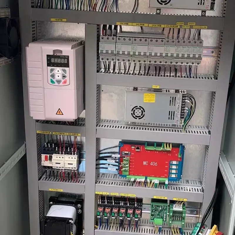
The Correlation Between Inverter Protection Ratings and Environmental Factors The protection rating of a frequency inverter—typically denoted by an IP (Ingress Protection) code—is not a random specification. It is specifically engineered to counteract the impact of environmental conditions, and this direct correlation ensures the inverter operates reliably, avoids damage, and extends its service life. Understanding IP Codes for Inverters An IP code consists of two core digits, each representing a distinct protection capability: First digit (0–6): Measures resistance to solid particles (e.g., dust, debris). A higher number indicates stronger dust protection for the inverter. Second digit (0–9K): Evaluates resistance to liquids (e.g., droplets, splashes, immersion). A higher number means better water resistance for the inverter. How Environmental Factors Determine Inverter Protection Ratings Different environments pose unique threats to frequency inverters, requiring targeted IP ratings to mitigate risks. Below is a breakdown of key environmental scenarios and their corresponding protection requirements: 1. Dust-Prone Environments Environments with high concentrations of dust—such as flour mills, cement plants, and woodworking workshops—can cause internal component wear, short circuits, or heat dissipation failures if dust infiltrates the inverter. Recommended IP Rating: IP5X (dust-protected; dust entry will not affect inverter operation) or IP6X (fully dust-tight; no dust penetrates the inverter). 2. Humid or Water-Exposed Environments Moisture or water (e.g., splashes, spills, rain) poses a major risk of electrical short circuits for inverters. Common scenarios include food processing facilities (where equipment is cleaned with water), car wash stations, and outdoor inverter installations. Humid/splashing water: IPX4 or higher (protects the inverter against water splashes from any direction). Direct water spray (e.g., washing areas): IPX5 or IP6X (resists low-pressure or high-pressure water jets to protect the inverter). Short-term immersion (special cases): IPX7 (the inverter survives immersion in 1 meter of water for up to 30 minutes). 3. Extreme Temperature Environments...
Details
09/16/2025
Factors to Consider When Selecting an Inverter: Environmental Aspects When selecting an inverter, environmental factors directly determine its operational stability, service life, and safety. Neglecting these factors may lead to frequent failures (such as overheating, short circuits, and corrosion) or even equipment damage. The following 6 core environmental factors require focused attention, and some factors need quantitative evaluation based on specific application scenarios: 1. Temperature: A Core Factor Affecting Heat Dissipation and Component Life Temperature is one of the most sensitive environmental factors for inverters. Internal components such as power modules (e.g., IGBTs) and capacitors are highly sensitive to temperature changes. Exceeding the allowable temperature range will directly shorten the service life or trigger protective shutdowns. Operating Temperature Range: The recommended operating temperature for conventional inverters is -10°C to 40°C (some industrial-grade models can extend this range to -20°C to 50°C). Priority should be given to models that match the on-site temperature. If the on-site temperature exceeds 40°C, the inverter’s service life will shorten by approximately 2% to 3% for every 1°C increase. When the temperature is below 0°C, the fluidity of capacitor electrolyte decreases, which may cause startup failures. In such cases, models with “low-temperature startup protection” or “preheating function” should be selected. Installation Requirements: Avoid installing the inverter near heat sources (e.g., boilers, ovens, high-power motors). If avoidance is impossible, reserve a heat dissipation distance of at least 30 cm and add forced ventilation (e.g., installing cooling fans). For outdoor or high-temperature environments (e.g., metallurgical plants, coking plants), select “high-temperature protective inverters” or equip them with thermal insulation and sunshades (to prevent sudden temperature rises in the cabinet due to direct sunlight). 2. Humidity: Preventing Insulation Breakdown and Short Circuits Excessively high humidity can cause moisture absorption in the inverter’s internal circuit boards, reduce insulation performance, and even lead...
Details

09/15/2025
Common Faults of Inverters and Their Troubleshooting Guide During long-term operation, inverters are prone to various faults due to factors like load conditions, environmental influences, parameter misconfigurations, and hardware aging. Below is a detailed breakdown of six core fault categories—overcurrent, overvoltage, overload, overheating, no output/output abnormality, and communication faults—including their common symptoms, typical causes, and basic troubleshooting steps to help you quickly identify and resolve issues: 1. Overcurrent Fault (Most Common, e.g., Error Codes ERR10, OC) Common Symptoms The inverter triggers an “overcurrent” error (codes vary by brand, such as Delta’s OC, Mitsubishi’s ERR10) and shuts down automatically to protect the system. Typical Causes Load-side issues: Short circuits or ground faults in motor windings (caused by insulation damage); jamming of mechanical transmission parts (e.g., seized bearings, overly tight belts) that leads to motor stalling. Wiring issues: Loose, short-circuited, or grounded cables between the inverter and motor (e.g., damaged cable insulation touching the machine casing). Parameter misconfigurations: Excessively short acceleration time (resulting in a sudden spike in motor startup current); mismatched motor rated current settings (the set value is lower than the motor’s actual rated current). Hardware failures: Damaged internal power modules (e.g., IGBTs); malfunctions in current detection circuits (e.g., faulty Hall sensors). Basic Troubleshooting After turning off the power, use a multimeter to measure the motor’s winding resistance—normal readings show balanced resistance across three phases with no ground short circuit. Check if transmission components move freely and ensure cable connections are secure and undamaged. Verify that the inverter’s motor parameters (rated current, voltage) and acceleration time settings match the motor’s specifications. 2. Overvoltage Fault (e.g., Error Codes OV, OU) Common Symptoms The inverter displays an “overvoltage” error (e.g., Siemens’ OU, Schneider’s OV), which often occurs when the motor decelerates or stops abruptly. Typical Causes Power supply fluctuations: Abnormally high grid voltage...
Details
09/15/2025
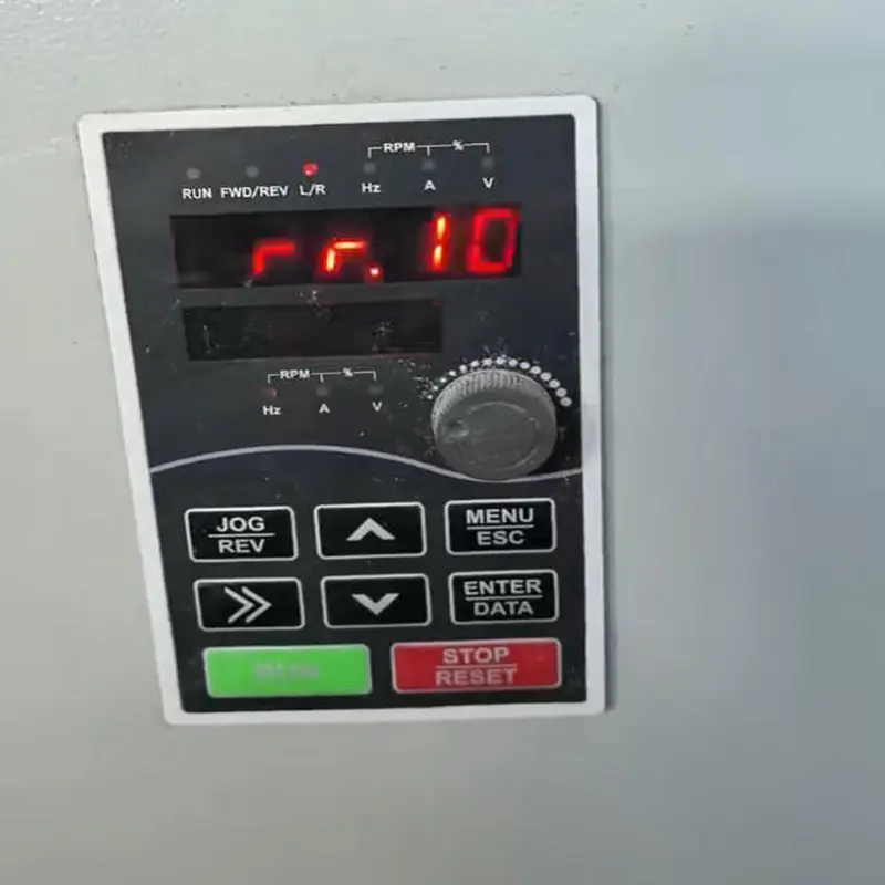
How to Troubleshoot “ERR10” Fault on an Inverter? The “ERR10” fault code on an inverter typically indicates an overcurrent fault—one of the most common issues encountered during inverter operation. When this error occurs, follow these steps to troubleshoot and resolve the problem: 1. Stop the Machine Immediately for Inspection First, cut off the inverter’s power supply. Wait a few minutes, then restart it to check if the fault is occasional (i.e., a one-time glitch). 2. Inspect the Motor and Load Check if the motor is running under overload or if the load has increased suddenly. Verify whether the motor windings are short-circuited or grounded; use a multimeter to measure the motor’s winding resistance for confirmation. Examine if mechanical transmission components are jammed, as this can cause the motor to stall (and trigger the overcurrent fault). 3. Check Wiring Connections Inspect the wires connecting the inverter to the motor for looseness, short circuits, or unintended grounding. Check if terminal blocks are oxidized or have poor contact, as both issues can disrupt current flow and trigger false faults. 4. Verify Parameter Settings Confirm that the inverter’s parameters match the motor’s specifications, such as the motor’s rated current and rated voltage. Mismatched parameters often lead to overcurrent. Check if the acceleration time is set too short. If so, extend the acceleration time parameter appropriately—rapid acceleration can overload the motor and trigger ERR10. 5. Inspect the External Environment Check if the ambient temperature around the inverter is too high, if its heat dissipation system is functioning effectively, and if the cooling fan is working properly. Overheating can impair current regulation and cause false overcurrent alerts. Check for electromagnetic interference (EMI) in the area, as EMI can disrupt the inverter’s internal circuits and lead to incorrect fault codes. 6. Troubleshoot Internal Hardware Faults If all the...
Details
09/12/2025
Why Are Single-Phase Input Inverters Unsuitable for High-Power Equipment? Single-phase input inverters are unsuitable for high-power equipment, primarily due to limitations in input capacity, current stress, DC bus ripple, grid compliance, and cost-effectiveness. These constraints make it challenging to deliver stable, efficient, and compliant operation when handling high power loads. Key Reasons Overview Limiting Factor Specific Performance Impact on High-Power Operation Input Power Supply Capacity & Current Single-phase power supplies have inherent limits on the current and apparent power they can deliver. High-power equipment demands large currents, which often causes single-phase circuits to overload and experience significant voltage drops. Rectifier Bridge & Component Stress Single-phase rectification only uses two phases for conduction, leading to higher peak and average currents. This creates excessive current stress on rectifier bridge arms and capacitors, requiring significant derating (typically to around 2/3 of the rated capacity). DC Bus Ripple Single-phase rectification results in fewer voltage zero-crossing events, generating larger voltage ripple on the DC bus. To mitigate this, larger capacitors and more robust heat dissipation systems are needed—both of which increase the inverter’s size and cost. Three-Phase Grid Imbalance & Harmonics High-power single-phase loads often disrupt three-phase grid balance and cause harmonic levels to exceed regulatory limits. Additional harmonic suppression and imbalance correction measures become necessary, raising operational, maintenance, and compliance costs. Efficiency & Heat Dissipation High currents and excessive bus ripple lead to greater power losses and heat generation within the inverter. This reduces overall efficiency, lowers long-term reliability, and requires more powerful cooling solutions to prevent overheating. Cost & Practicality Scaling single-phase inverters for high power requires oversized components and cooling systems. The resulting unit cost and physical size end up being comparable to three-phase alternatives, making single-phase options economically unviable. Why Not Simply “Scale Up” Single-Phase Inverters? Component Stress & Cooling Limits:...
Details
09/12/2025
How to Determine Which Inverter to Choose Based on Load Characteristics In industrial scenarios, the core of inverter selection lies in “matching load characteristics”—different loads vary significantly in torque, speed, impact resistance, and other properties. Improper selection can lead to low equipment efficiency, frequent failures, or even burnout. Starting from the classification of load characteristics, this article clarifies the corresponding selection logic for DreamWe inverters by aligning with the core requirements of various loads, and includes typical application cases to help users accurately match the right inverter solution. 1. First, Clarify the Core Classification of Load Characteristics: 3 Basic Types The key distinction between load characteristics lies in the “relationship between torque and speed“. The most common industrial loads fall into three categories, and their traits directly define the functional requirements for inverters: Load Type Core Characteristic (Torque-Speed Relationship) Typical Application Scenarios Constant Torque Load Torque remains consistent and independent of speed (load torque stays nearly unchanged regardless of speed); high starting torque is required during startup Lifting equipment (cranes, elevators), conveyors, extruders, mixers Constant Power Load Power remains stable, and torque is inversely proportional to speed (higher speed leads to lower torque; torque is extremely high at low speeds) Lathes, milling machines, grinders (metal cutting), winders (late-stage winding) Quadratic Law Load Torque is proportional to the square of speed, and power is proportional to the cube of speed (torque is low at low speeds and rises rapidly at high speeds) Fans, water pumps, cooling towers, ventilators 2. Matching DreamWe Inverters Based on Load Characteristics: Scenario-Specific Selection Guide Different loads have distinct demands for an inverter’s “torque response speed, overload capacity, speed regulation range, and energy-saving features”. As such, it is essential to select DreamWe inverter models in a targeted manner: 1. Constant Torque Loads: Prioritize DreamWe Inverters with “High Overload Capacity and Fast Torque Response”...
Details
09/12/2025
Advantages of DTC Technology in Lifting Equipment DTC (Direct Torque Control) technology, as an advanced inverter control method, enables the direct and precise regulation of motor torque and flux. It effectively addresses the pain points of traditional control technologies—such as slow response speeds, poor stability, and low energy efficiency—when applied to lifting equipment. Its core advantages can be elaborated from five key dimensions: operational efficiency, control precision, adaptability to working conditions, system maintenance, and economic benefits, as detailed below: 1. Operational Efficiency: Fast and Accurate Torque Response to Reduce Idle Waiting The core requirement of lifting equipment is frequent start-stops and rapid load changes (e.g., lifting/lowering heavy objects, adjusting operating positions), which demands an extremely high dynamic torque response speed.DTC technology eliminates the need for complex coordinate transformations (such as the rotational transformation used in traditional vector control) and the simplification of motor mathematical models. Instead, it calculates and controls electromagnetic torque directly in the stator coordinate system, achieving a dynamic response speed of < 2ms—far faster than the tens of milliseconds required by traditional control systems. Practical Scenario: When lifting steel bars or cement at construction sites, DTC technology allows cranes to respond instantly to “lifting” commands. It quickly increases torque to meet load requirements, avoiding the waiting time caused by the “slow start” of traditional systems. Compared with traditional control methods, operational efficiency can be improved by approximately 30%, making DTC particularly suitable for high-frequency, fast-paced lifting operations. 2. Control Precision: Precise Speed and Position Regulation to Ensure Operational Safety In precision lifting scenarios (e.g., transporting high-value equipment, fragile components, or installing precision instruments), “zero sway and high-precision positioning” are critical.DTC technology uses stator flux orientation and directly adjusts stator flux and electromagnetic torque via a two-position “bang-bang controller,” enabling: Precise Low-Speed Control: Even when heavy objects move at an extremely...
Details
09/11/2025
How to Enhance the Robustness of Vector Control and Direct Torque Control In AC motor speed control systems, Vector Control (VC) and Direct Torque Control (DTC) are two mainstream high-performance control strategies. However, they differ in sensitivity to parameter perturbations, load disturbances, and external interferences. Targeted optimizations are required to improve their robustness—defined as a system’s ability to maintain stability and control accuracy under disturbances. Below is a detailed breakdown of “core challenge analysis” and “strategy-specific optimization methods,” combined with technical pathways and theoretical details, to systematically explain robustness enhancement solutions. I. First, Clarify: Core Robustness Challenges of VC and DTC The root cause of insufficient robustness lies in the “deviation between the control model/target and the actual system state.” The core pain points of the two strategies differ and must be addressed specifically: Control Strategy Core Control Logic Robustness Weaknesses Typical Disturbance Scenarios Vector Control (VC) Based on “field orientation,” it decomposes the stator current into an excitation component (id) and a torque component (iq), which are independently controlled via PI regulators. It relies on accurate motor parameters (e.g., stator resistance Rs, rotor resistance Rr, leakage inductance σL, mutual inductance Lm) to build a mathematical model. 1. Strong parameter dependence: Rotor resistance Rr changes with temperature (e.g., Rr can increase by 2–3 times at a temperature rise of 200°C), and mutual inductance Lm changes with magnetic saturation—both directly causing field orientation deviations.2. Dynamic lag of the current loop: Traditional PI regulators have a slow response to sudden load changes, easily leading to overshoot or steady-state errors.3. Grid voltage disturbances: Voltage sags or imbalances cause coupling between id and iq, disrupting decoupled current control. Long-term motor operation (parameter drift), frequent sudden load changes (e.g., machine tool cutting, elevator start/stop), low-voltage grid fluctuations. Direct Torque Control (DTC) Does not rely on precise field orientation. It directly selects...
Details
09/11/2025
How to Further Optimize the Performance of Vector Control (VC) and Direct Torque Control (DTC)? Vector Control (VC, also known as Field-Oriented Control, FOC) and Direct Torque Control (DTC) are the two core technologies for high-performance AC motor control in current applications. Although they differ in control logic—VC is based on “field orientation-current decoupling,” while DTC relies on “direct torque/flux hysteresis regulation”—their core goals for performance optimization are consistent: improving dynamic response speed, enhancing steady-state control accuracy, strengthening anti-interference capability, and reducing torque ripple and energy loss. Below is a systematic explanation of performance improvement solutions, divided into “common optimization strategies” and “targeted optimization strategies.” I. Common Optimization Strategies for Both Vector Control (VC) and Direct Torque Control (DTC) The performance bottlenecks of both control technologies are directly related to “signal sensing accuracy,” “control algorithm robustness,” and “hardware execution efficiency.” These bottlenecks can be addressed through the following universal methods: 1. Optimize Motor State Observation and Feedback Accuracy The measurement/estimation accuracy of core motor state signals—such as speed, rotor position, stator current, and flux—serves as the “foundation” of control performance. Errors in these signals directly lead to field orientation deviations (in VC) or inaccurate torque calculation (in DTC), resulting in torque ripple. Selection of High-Precision Sensors: Prioritize photoelectric encoders with a resolution of 17 bits or higher (suitable for servo scenarios) or resolvers (ideal for high-temperature, high-vibration industrial/automotive environments) instead of low-precision Hall sensors. For current sampling, use high-precision shunt resistors (±0.1%) or Hall current sensors paired with ADC chips of 16 bits or higher to reduce sampling noise. Improvement of Observer Algorithms: If high-precision sensors cannot be used due to cost or installation space constraints, optimize sensorless observers: At low speeds: Replace traditional sliding mode observers with the “high-frequency injection method” to reduce flux observation errors (especially for VC...
Details
09/11/2025
When Is Vector Control Suitable for Use? Vector Control, also known as Field-Oriented Control (FOC), is a high-performance motor control technology that achieves independent regulation of motor torque, speed, and magnetic flux by precisely controlling the amplitude and phase of the motor stator current. Its core advantages include fast dynamic response, high steady-state accuracy, and smooth torque control—making it ideal for scenarios that demand strict motor control performance. Below is a detailed breakdown of when to use vector control, organized by three key dimensions: application scenarios, core requirements, and motor types. 1. Core Requirements: Scenarios Needing “Fast Dynamic Response” and “High Control Accuracy” When a system must quickly and accurately adjust motor states (e.g., speed, torque) or maintain stable control even amid drastic load changes—where traditional methods (such as V/F control) fail to deliver—vector control emerges as the optimal solution. 1.1 Scenarios Requiring Fast Dynamic Response Servo Drive Systems: This includes industrial robot joints, CNC machine tool spindles/feed axes, and robotic arms in automated assembly lines. These applications demand the motor to switch between “startup-acceleration-emergency stop-reversal” in milliseconds (e.g., rapid positioning when a robot grabs a workpiece). Vector control enables fast, overshoot-free responses by independently adjusting the torque component, preventing workpiece wobble or positioning errors. Elevator/Lift Drives: Elevators need to reach rated speed quickly during startup and decelerate precisely when stopping (to avoid “topping” or “bottoming” of the car), while the load (number of passengers) changes in real time. Vector control dynamically compensates for torque based on load variations, ensuring smooth startups, precise stops, and reduced operating noise. Electric Vehicle (EV)/New Energy Vehicle (NEV) Drives: During vehicle startup, acceleration for overtaking, or brake energy recovery, the motor must respond quickly to the driver’s inputs (e.g., minor changes to the accelerator pedal) across a wide speed range. Vector control delivers linear torque...
Details

09/10/2025
Differences Between Vector Control and Direct Torque Control Vector Control (VC) and Direct Torque Control (DTC) are two core control strategies in the field of high-performance speed regulation for AC motors—especially induction motors and permanent magnet synchronous motors. Both take “decoupling control” as their core goal, but they differ significantly in control philosophy, implementation approach, and performance characteristics. Below is a systematic comparison of their differences across dimensions such as core principle, control logic, key components, and performance indicators, along with additional recommendations for applicable scenarios. 1. Core Principle: “Indirect Decoupling” vs. “Direct Control” The fundamental difference between the two lies in their control logic for the motor’s core physical quantities (flux linkage and torque), as detailed in the table below: Control Strategy Core Philosophy Decoupling Method Implementation Path for Control Objectives Vector Control (VC) It emulates the control logic of DC motors: the stator current of an AC motor is decomposed into an “excitation component (i_d)” and a “torque component (i_q)”. Decoupling of torque and flux linkage is achieved by independently controlling these two orthogonal components. Indirect Decoupling: Through “coordinate transformations” (e.g., Clark transformation, Park transformation), three-phase AC quantities are converted into DC quantities in a synchronous rotating coordinate system. PID regulation is then applied to these DC quantities to control torque indirectly. 1. Detect the motor’s current and speed;2. Obtain i_d and i_q via coordinate transformation;3. Perform closed-loop control on i_d (to track the specified flux linkage value) and i_q (to track the specified torque value) separately;4. Generate inverter switching signals through inverse transformation. Direct Torque Control (DTC) It controls the “stator flux linkage” and “electromagnetic torque” of the motor directly in the stationary coordinate system without the need for coordinate transformation. By judging real-time deviations of flux linkage and torque and selecting the optimal voltage vector, deviations are corrected...
Details
09/10/2025
Advantages of Inverter V/F Control V/F control (Voltage-Frequency Control), also known as “constant V/F ratio control,” is a classic and widely used AC motor speed regulation technology. Its core principle is maintaining a constant ratio of output voltage to frequency (V/F) when adjusting the motor speed—this ensures the motor’s magnetic flux remains stable, avoiding magnetic saturation or insufficient torque. Compared with high-performance control methods like vector control, V/F control stands out for its simplicity, cost-effectiveness, and reliability, making it the preferred choice for many general industrial scenarios. Below are its six key advantages: 1. Simple Control Principle & Low Technical Threshold V/F control does not rely on complex coordinate transformations, motor mathematical models, or high-precision feedback devices (e.g., encoders). Its control logic only requires proportional adjustment of output voltage and frequency based on the set speed, which greatly reduces the difficulty of circuit design and software programming. Application Benefit: Engineers can quickly master debugging and maintenance without in-depth knowledge of motor dynamics. It is especially suitable for small and medium-sized enterprises or scenarios with limited technical reserves. 2. Low Hardware Cost & Wide Compatibility Since V/F control does not require additional feedback modules (such as speed encoders or current sensors) or high-performance microprocessors (for complex calculations), the overall hardware cost of the inverter is significantly lower than that of vector control inverters. Compatibility Advantage: It works with almost all types of AC asynchronous motors (e.g., single-phase, three-phase, low-power, or high-power motors) without the need for motor parameter identification or matching. This eliminates “customization” costs and simplifies the replacement or upgrade of old motors. 3. High System Reliability & Strong Anti-Interference Capability The simplicity of V/F control reduces the number of system components and the complexity of signal transmission, thereby minimizing the risk of faults caused by component failures...
Details